Juniper Advanced Junos Enterprise Switching (AJEX) notes
![]()
Vlans
By default all interfaces are Access Ports assigned to VLAN 1.
Access Ports
- Connects to end-user devices
- Carry untagged traffic
- Associated with single vlan
1
2
set interfaces ge-0/0/8 unit 0 family ethernet-switching interface-mode access
set interfaces ge-0/0/8 unit 0 family ethernet-switching vlan members 10
1
2
set interfaces ge-0/0/9 unit 0 family ethernet-switching interface-mode access
set interfaces ge-0/0/9 unit 0 family ethernet-switching vlan members 20
Trunk Ports
- Connect to other switches
- Carry tagged traffic
- Associated with multiple vlans
1
2
3
4
5
6
7
set interfaces ge-0/0/12 unit 0 family ethernet-switching interface-mode trunk
set interfaces ge-0/0/12 unit 0 family ethernet-switching vlan members [ v10 v20 ]
set interfaces ge-0/0/12 native-vlan-id X

or

set interfaces ge-0/0/12 unit 0 family ethernet-switching vlan members all
CLI commands available
1
2
3
4
5
6
7
8
{master:0}[edit] user@Switch-1# set vlans ?
+ community-vlans List of VLAN id or name description Text description of VLANs
> forwarding-options Forwarding options configuration
> interface Interface name for this VLAN isolated-vlan VLAN id or name l3-interface L3 interface name for this vlans mcae-mac-flush Enable IRB MAC flush in a/s mode for this VLAN on MCAE link up mcae-mac-synchronize Enable IRB MAC synchronization in this VLAN
> multicast-snooping-options Multicast snooping option configuration no-irb-layer-2-copy Disable transmission of layer-2 copy of packets of IRB private-vlan Type of secondary vlan for private vlan service-id Service id required if VLAN is of type MC-AE, and vlan-id all or vlan-id none or vlan-tags is configured
> switch-options VLANs switch-options configuration vlan-id IEEE 802.1q VLAN identifier for VLAN (1..4094)
+ vlan-id-list Create VLAN for each vlan-id specified in the vlan-id-list
> vxlan
P-VLAN
Private VLANs:
- Enables to split a broadcast domain into multiple isolated broadcast subdomains. Essentially a VLAN inside a VLAN.
- The Primary VLAN can have one or more Secondary VLANs nested inside.
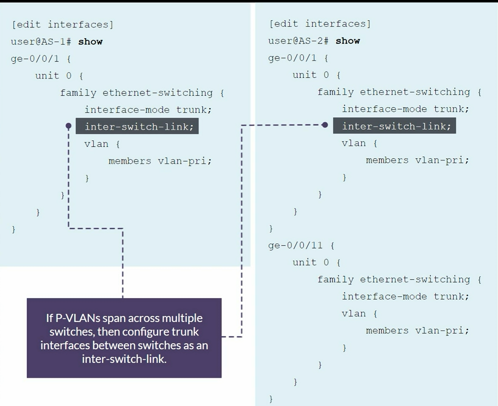
- Can be configured on a single switch or to span multiple switches.
- The P-VLAN feature is not supported on all EX Series switches.
- Cannot enable both the voice VLAN and P-VLAN feature at the same time on the same interface
The primary VLAN is the central VLAN for a P-VLAN.
- The primary VLAN always includes an 802.1Q tag.
- Secondary VLANs can be community or isolated VLANs and are nested inside the primary VLAN.
- Community VLAN: Transports frames among interfaces within the same community and forwards frames upstream to the primary VLAN.
- Isolated VLAN: Receives packets only from the primary VLAN and forward frames to the primary VLAN. It can be used when a P-VLAN is configured on one switch or spans multiple switches in a P-VLAN domain.
- Inter-switch isolated VLAN: Used to forward isolated VLAN traffic from one switch to another through
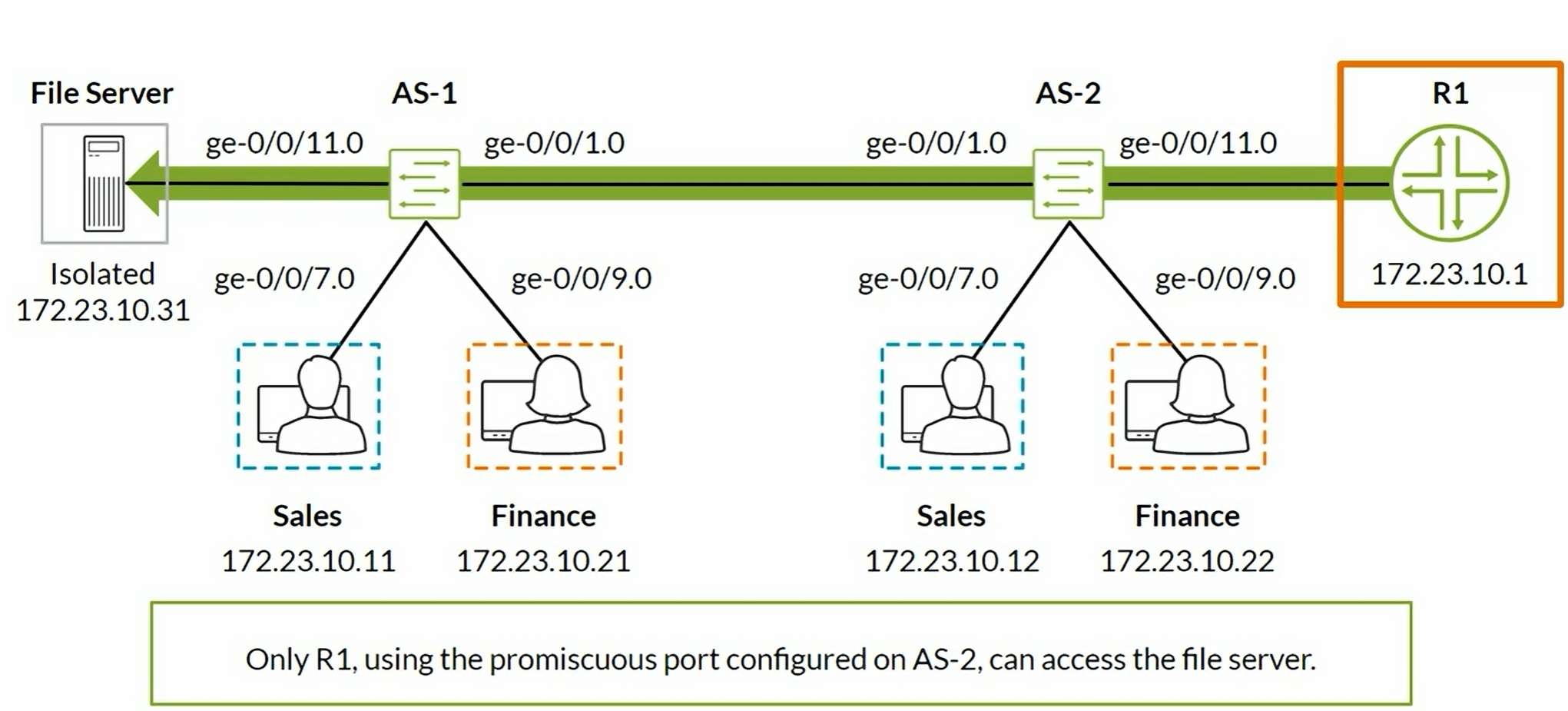
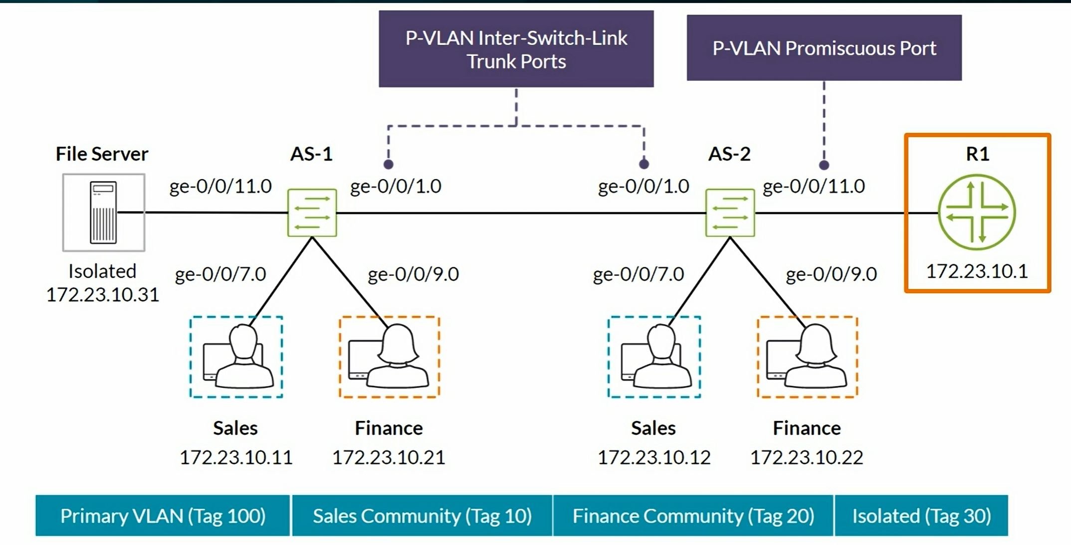
pvlan-trunkports. Used when the P-VLAN spans multiple switches. - Promiscuous ports: Trunk ports that are typically connected to a Router. These ports have Layer 2 connectivity to all other switch ports, including isolated ports.
- Secondary VLANs are not required to include 802.1Q tag unless the P-VLAN spans multiple switches.
Summary:
- Promiscuous port. Upstream trunk port that connects to a Router, Firewall, etc. No secondary VLAN on this one. Can communicate to any Community and Isolated secondary VLAN.
- Community ports to form groups of users within the same VLAN. They communicate among themselves as long as they are on the same Secondary VLAN. Can communicate with Promiscuous port.
- Isolated port have Layer 2 connectivity only with Primiscuous ports and
pvlan-trunkports. - PVLAN-Trunk port. Connects 2 Switches participating in the same P-VLAN domain. Communicates with all ports except isolated ports.
Tshoot commands
1
2
3
show vlans
show vlans extensive <PRIMARY-VLAN-NAME>
show vlans extensive <SECONDARY-VLAN-NAME>
Dynamic VLAN Registration
MVRP - Multiple VLAN Registration Protocol. Dynamically manages VLAN registration on a LAN. Prunes VLAN information on Trunk ports when a Switch has no active access ports for a configured vlan. It can also be used to dynamically create VLANs in Switching networks. MVRP replaces GVRP.
MVRP can only be enabled on Trunk interfaces. MVRP does not support all Spanning-Tree Protocols (STPs). Currently, MVRP does not support the VLAN Spanning Tree Protocol (VSTP).
NOTE: There is an MVRP “extra byte” incompatibility in old vs new versions of Junos OS. Check the documentation in case of doubt.
Configuration
- Configure all VLANs in the Access Switch.
- Trunk ports are configured as usual but do not allow any VLAN on it.
- Enable MVRP and specify the trunk/uplink ports.
1
2
set protocols mvrp interface ge-0/0/x.0
set protocols mvrp interface ge-0/0/y.0
Monitoring commands:
1
2
3
4
show mvrp
show mvrp dynamic-vlan-memberships
show mvrp statistics
show vlans
Layer 2 Tunnel Traffic
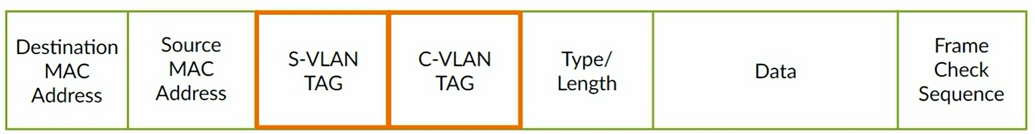
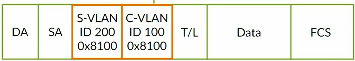
Q-in-Q tunneling is defined in IEEE 802.1ad. Stacked VLAN tags:
- Service VLAN (S-VLAN): controlled by the service provider
- Customer VLAN (C-VLAN): typically controlled by the customer
Configuration using Bundling Method
C-VLAN interface (towards end-customer)
1
2
3
4
5
6
set interfaces ge-0/0/7 flexible-vlan-tagging
set interfaces ge-0/0/7 native-vlan-id 10
set interfaces ge-0/0/7 encapsulation extended-vlan-bridge
set interfaces ge-0/0/7 unit 100 vlan-id-list 1-25
set interfaces ge-0/0/7 unit 100 input-vlan-map push
set interfaces ge-0/0/7 unit 100 output-vlan-map pop
S-VLAN interface (towards the provider)
1
2
3
set interfaces ge-0/0/1 flexible-vlan-tagging
set interfaces ge-0/0/1 encapsulation extended-vlan-bridge
set interfaces ge-0/0/1 unit 100 vlan-id 100
Configuration using Many-to-Many method
C-VLAN interface (towards end-customer)
1
2
3
4
5
6
7
8
9
set interfaces ge-0/0/7 flexible-vlan-tagging
set interfaces ge-0/0/7 native-vlan-id 10
set interfaces ge-0/0/7 encapsulation extended-vlan-bridge
set interfaces ge-0/0/7 unit 100 vlan-id-list 1-25
set interfaces ge-0/0/7 unit 100 input-vlan-map push
set interfaces ge-0/0/7 unit 100 output-vlan-map pop
set interfaces ge-0/0/7 unit 200 vlan-id-list 1-25
set interfaces ge-0/0/7 unit 200 input-vlan-map push
set interfaces ge-0/0/7 unit 200 output-vlan-map pop
S-VLAN interface (towards the provider)
1
2
3
4
set interfaces ge-0/0/1 flexible-vlan-tagging
set interfaces ge-0/0/1 encapsulation extended-vlan-bridge
set interfaces ge-0/0/1 unit 100 vlan-id 100
set interfaces ge-0/0/1 unit 200 vlan-id 200
Configuring specific C-VLAN to S-VLAN Mapping
C-VLAN interface (towards end-customer)
1
2
3
4
5
set interfaces ge-0/0/15 flexible-vlan-tagging
set interfaces ge-0/0/15 encapsulation extended-vlan-bridge
set interfaces ge-0/0/15 unit 300 vlan-id 125
set interfaces ge-0/0/15 unit 300 input-vlan-map swap
set interfaces ge-0/0/15 unit 300 output-vlan-map swap
Monitoring commands
1
2
show interfaces ge-0/0/7 extensive
show interfaces ge-0/0/7 detail
L2PT
1
set layer2-control mac-rewrite interface ge-0/0/7 protocol ?
Considerations:
- If you enable L2PT for untagged OAM LFM packets, do not configure LFM on the corresponding access interface
- If you enable L2PT for untagged LACP packets, do not configure LACP on the corresponding access interface
- CPD, UDLD, and VTP cannot be configured on EX Series switches. L2PT does, however, tunnel CDP, UDLD, and VTP PDUs.
Configuring an LACP interface
- Global command, allows X number of aggregated Ethernet interfaces to be created
1
set chassis aggregated-devices ethernet device-count 1
- Assign physical interface to the LAG interface
1
2
set interfaces ge-0/0/1 ether-options 802.3ad ae0
set interfaces ge-0/0/2 ether-options 802.3ad ae0
- Configure the LAG interface
1
2
set interfaces ae0.0 family ethernet-switching interface-mode trunk
set interfaces ae0.0 family ethernet-switching vlan members [v11 v12]
Configuring a P-VLAN
1
2
3
4
5
6
7
8
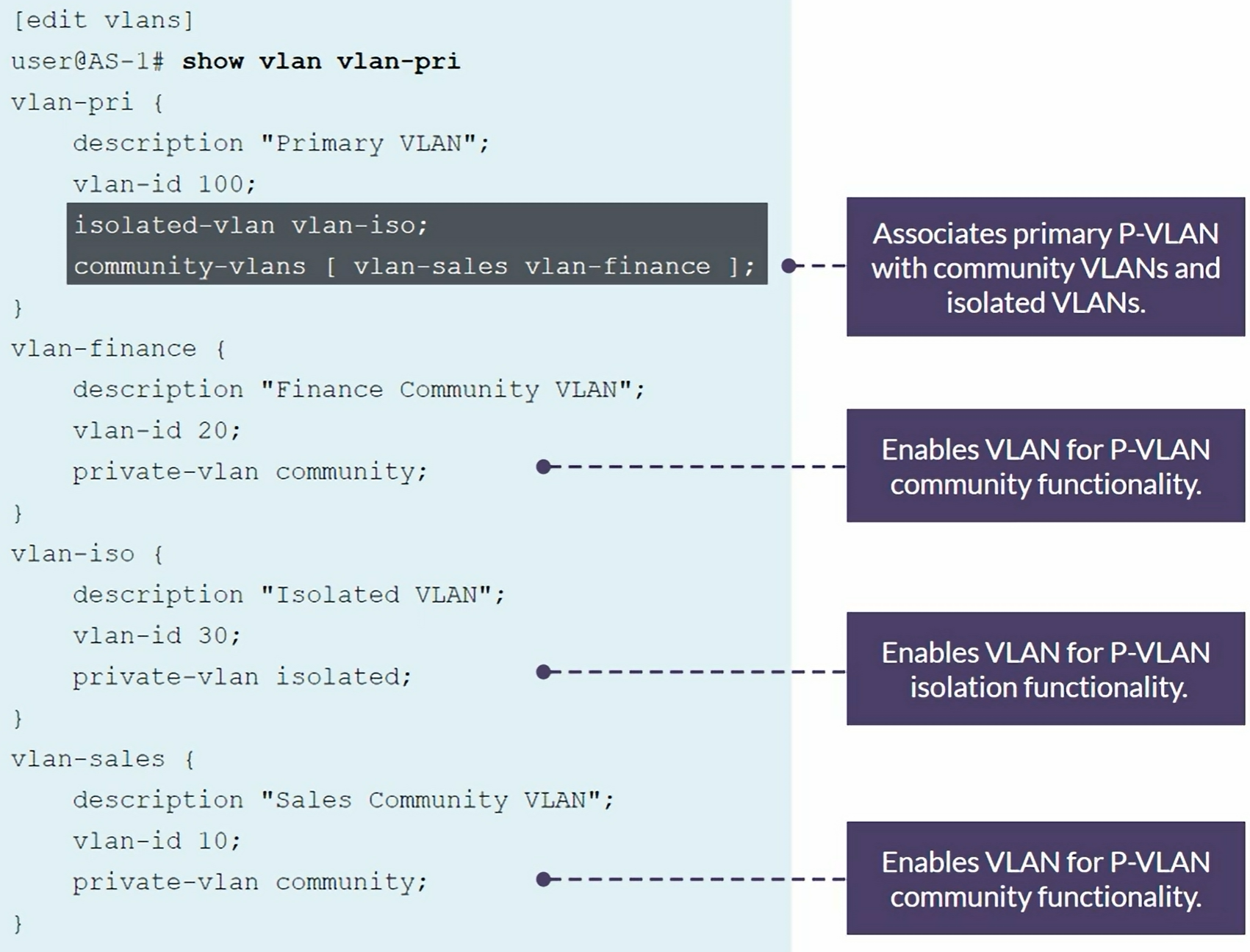
set vlans pvlan-50 description "Primary VLAN" vlan-id 50
set vlans pvlan-50 community-vlans [finance sales]
set vlans finance description "Community VLAN" vlan-id 41
set vlans finance private-vlan community
set vlans sales description "Community VLAN" vlan-id 42
set vlans sales private-vlan community
1
2
3
4
5
6
7
8
9
10
11
12
13
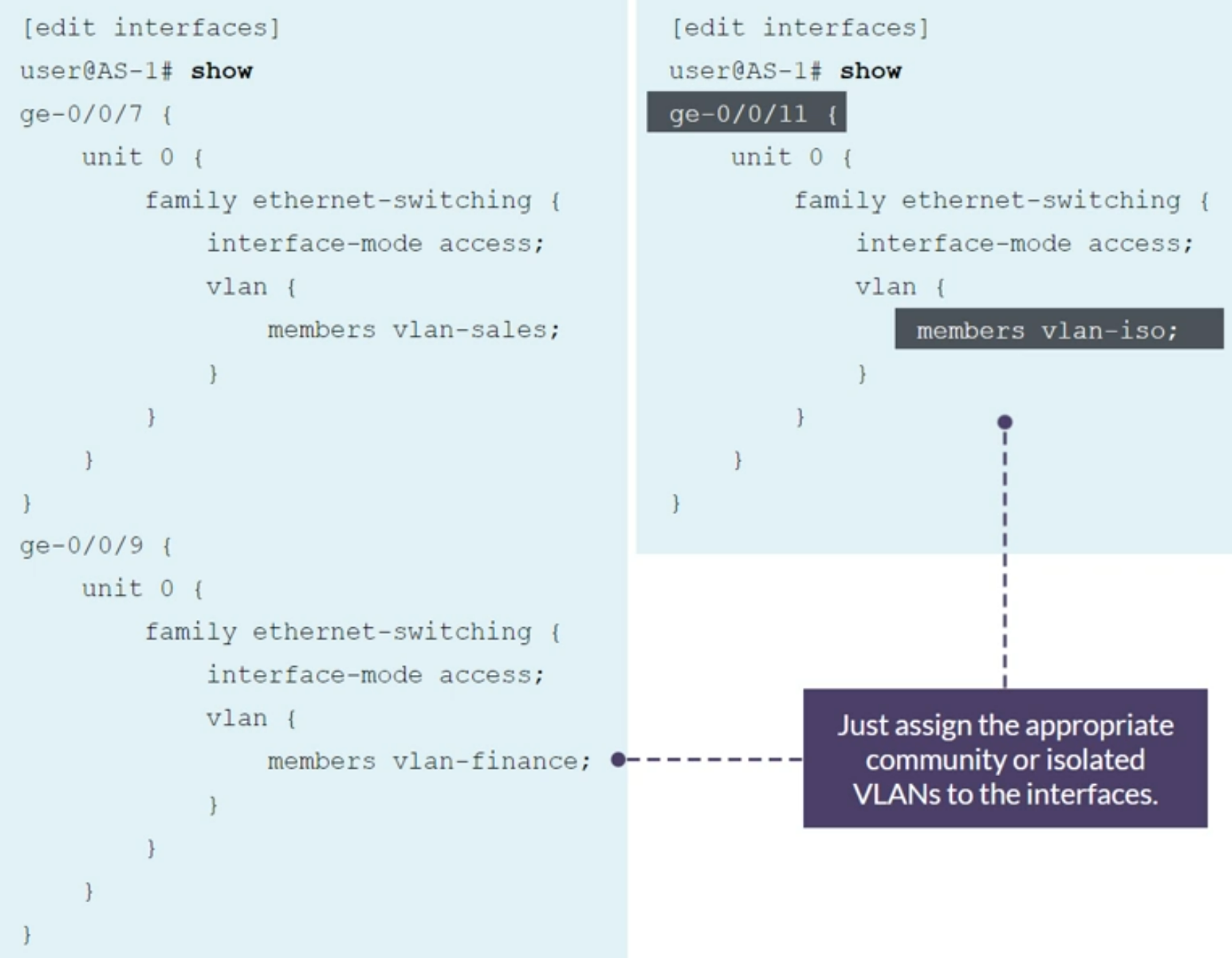
set interfaces ge-0/0/1 family ethernet-switching interface-mode access
set interfaces ge-0/0/1 family ethernet-switching vlan members finance
set interfaces ge-0/0/2 family ethernet-switching interface-mode access
set interfaces ge-0/0/2 family ethernet-switching vlan members finance
set interfaces ge-0/0/3 family ethernet-switching interface-mode access
set interfaces ge-0/0/3 family ethernet-switching vlan members sales
set interfaces ge-0/0/4 family ethernet-switching interface-mode access
set interfaces ge-0/0/4 family ethernet-switching vlan members sales
set interfaces ae0.0 family ethernet-switching interface-mode trunk
set interfaces ae0.0 family ethernet-switching inter-switch-link
set interfaces ae0.0 family ethernet-switching vlan members pvlan-50
Configuring MVRP
MVRP requires to use Spanning-Tree enabled on the Trunk interfaces that are configured for MVRP. It requires Rapid Spanning Tree Protocol (RSTP) or Multiple Spanning Tree Protocol (MSTP) enabled on the interface
1
2
set protocols rstp interface ae0
set protocols mvrp interface ae0
Verification commands
1
2
3
show vlans
show mvrp dynamic-vlan-memberships
show mvrp statistics
Configuring Q-in-Q tunneling
C-VLAN to use is 100 P-VLAN to use is 200
Port facing the end-customer
1
2
3
4
5
6
set interfaces ge-0/0/6 family ethernet-switching
set interfaces ge-0/0/6 flexible-vlan-tagging
set interfaces ge-0/0/6 encapsulation extended-vlan-bridge
set interfaces ge-0/0/6 unit 200 vlan-id-list 100
set interfaces ge-0/0/6 unit 200 input-vlan-map push
set interfaces ge-0/0/6 unit 200 output-vlan-map pop
Port facing the provider’s network
1
2
3
4
5
6
set interfaces ae0 family ethernet-switching
set interfaces ae0 flexible-vlan-tagging
set interfaces ae0 encapsulation extended-vlan-bridge
set interfaces ae0 unit 200 vlan-id 200
set interfaces ae0 unit 11 vlan-id 11
set interfaces ae0 unit 12 vlan-id 12
1
2
3
4
5
set vlans v100 interface ge-0/0/6.200
set vlans v100 interface ae0.200

set vlans v11 interface ae0.11
set vlans v12 interface ae0.12
MSTP - Multiple Spanning Tree Protocol
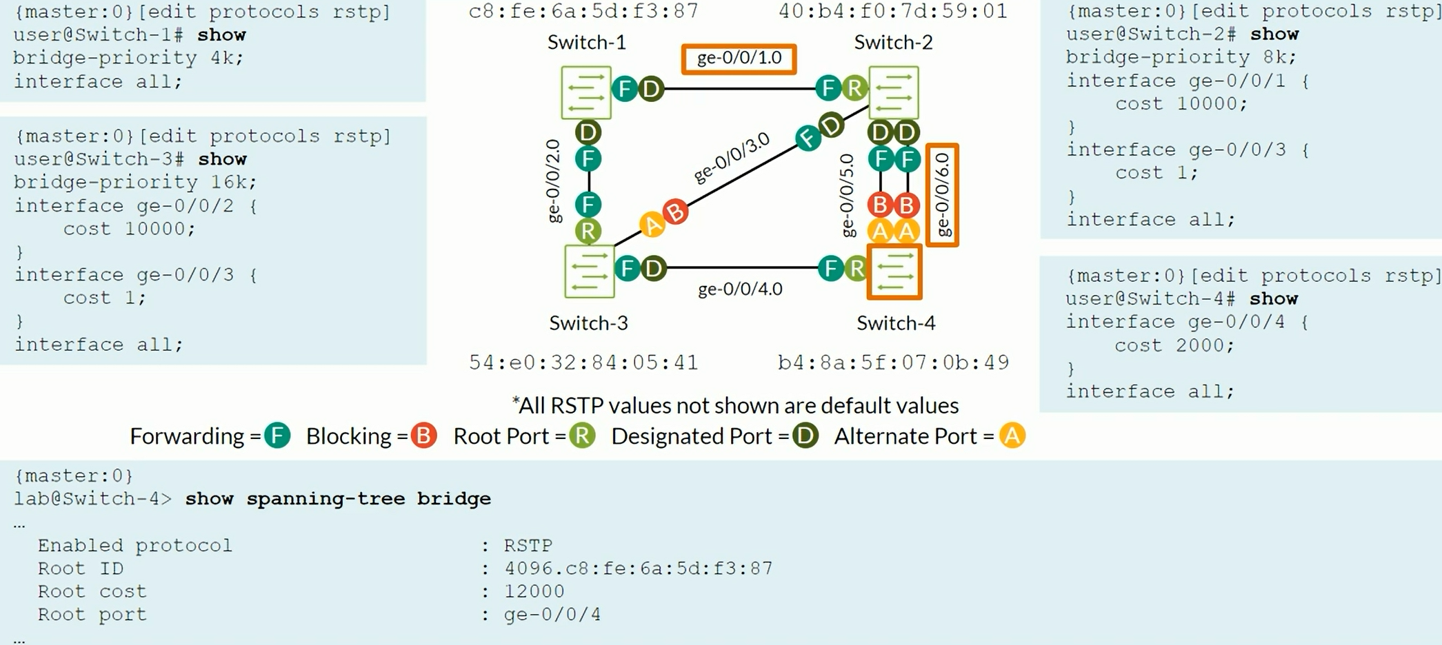
Switch with the least Bridge ID (Bridge Priority + MAC address) becomes the root bridge. Default Bridge Priority 32K by default.
The Root Bridge has all its port as Designated Ports (Forwarding State). STP cost on 1Gbps interfaces ge-0/0/x interfaces is 20,000 by default. Pord ID = Sender port priority + Sender interface number Port Priority is 128 by default.
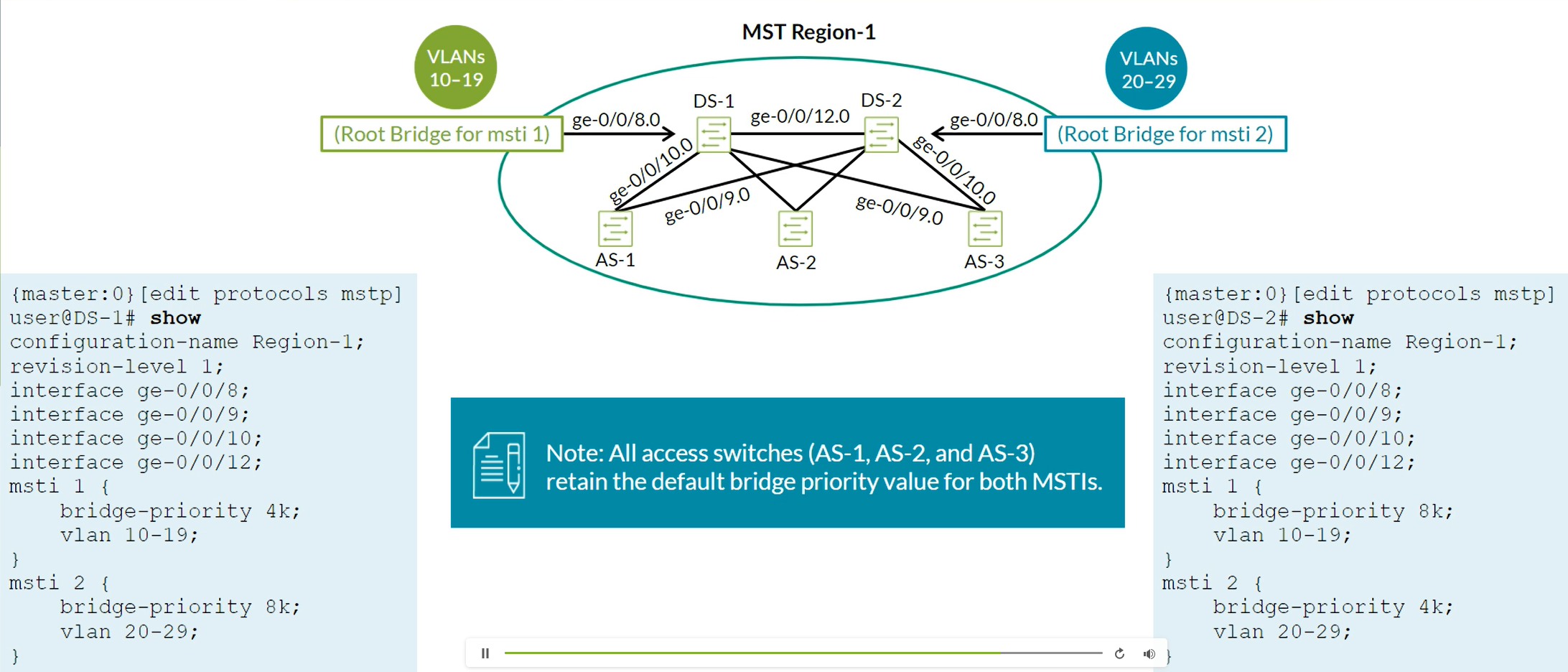
MSTP provides extension to RSTP. Enables you to create Multiple Spanning-Tree Instances (MSTIs) to balance traffic flows over all available links.
MSTP Regions are “clusters”. MSTP Regions shares same Region name, revision level and VLAN-to-instance mapping. You can configure a maximum of 64 MSTIs per MST region with one regional root bridge per instance.
Up to 64 MSTIs can be configured on each MST region.
Configuration of MSTP
MSTI 0 is the Common STP instance

1
2
3
4
5
show spanning-tree mstp configuration
show spanning-tree interface
show spanning-tree interface msti 1 detail
show spanning-tree interface msti 2 detail
show spanning-tree bridge
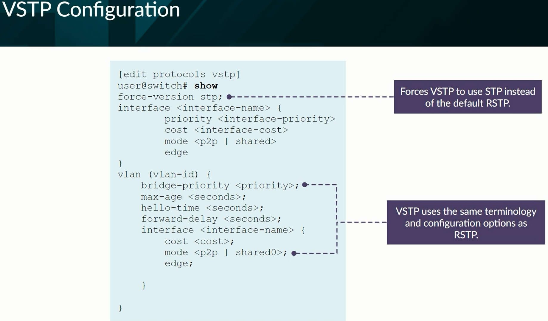
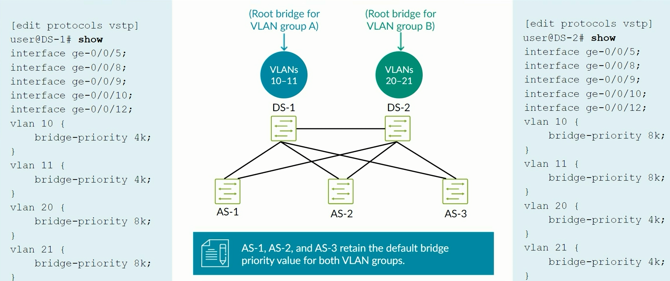
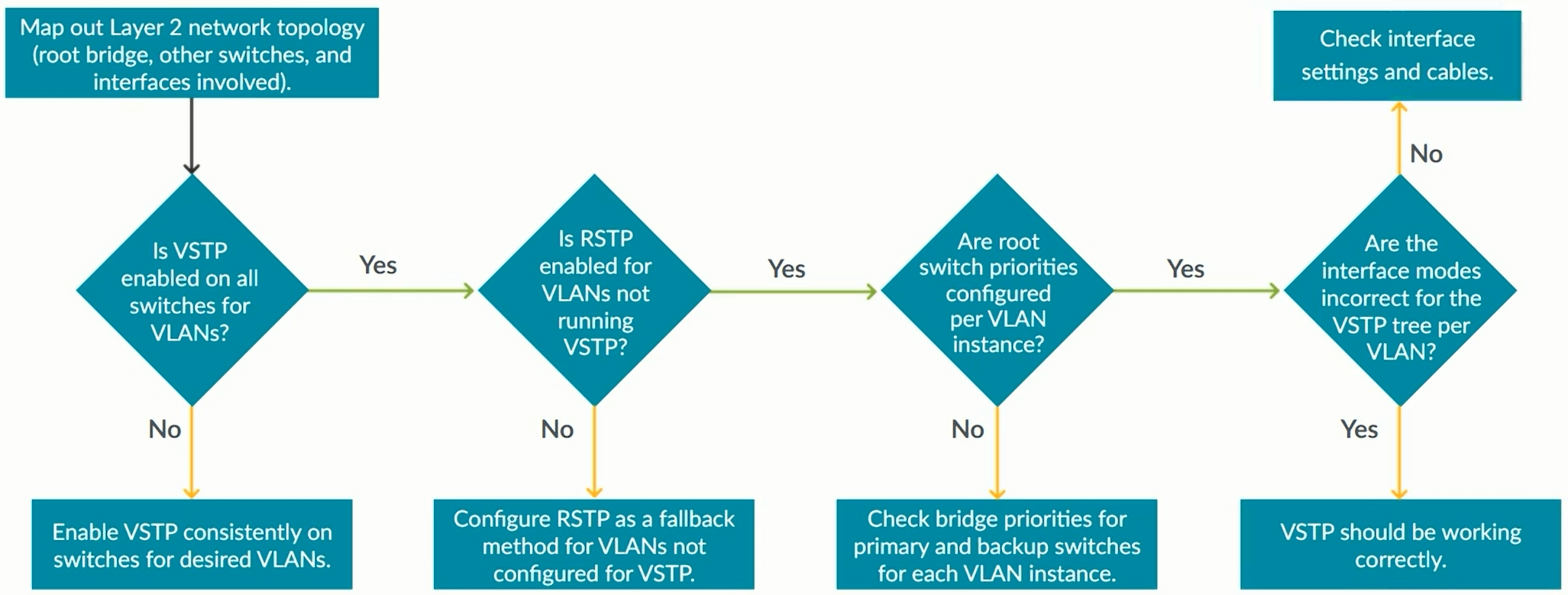
VSTP - VLAN Spanning Tree Protocol
VLAN Spanning Tree Protocol (VSTP) maintains a separate spanning-tree instance for each VLAN, enabling load balancing of Layer 2 traffic.
Proprietary protocol that is compatible with similar protocols from other vendors including:
- Per-VLAN Spanning Tree Plus (PVST+)
- Rapid-PVST+ (RPVST+)
Supports up to 253 different spanning-tree topologies
Rapid Spanning Tree Protocol (RSTP) can be enabled in addition to VSTP to account for any VLANs above and beyond 253.
Each STI (Spanning Tree Instance) will send their own BPDUs effectively making that each VLAN will send their own BPDUs.
Configuration of VSTP
1
2
3
show spanning-tree interface
show spanning-tree interface vlan-id XXX detail
show spanning-tree bridge
Authentication and Access Control
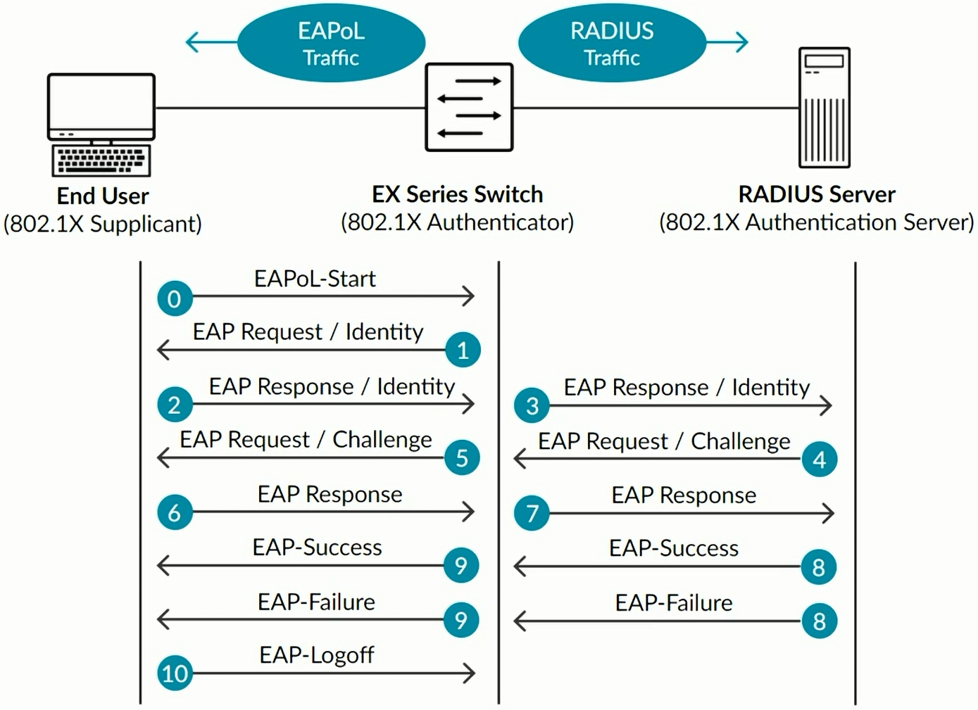
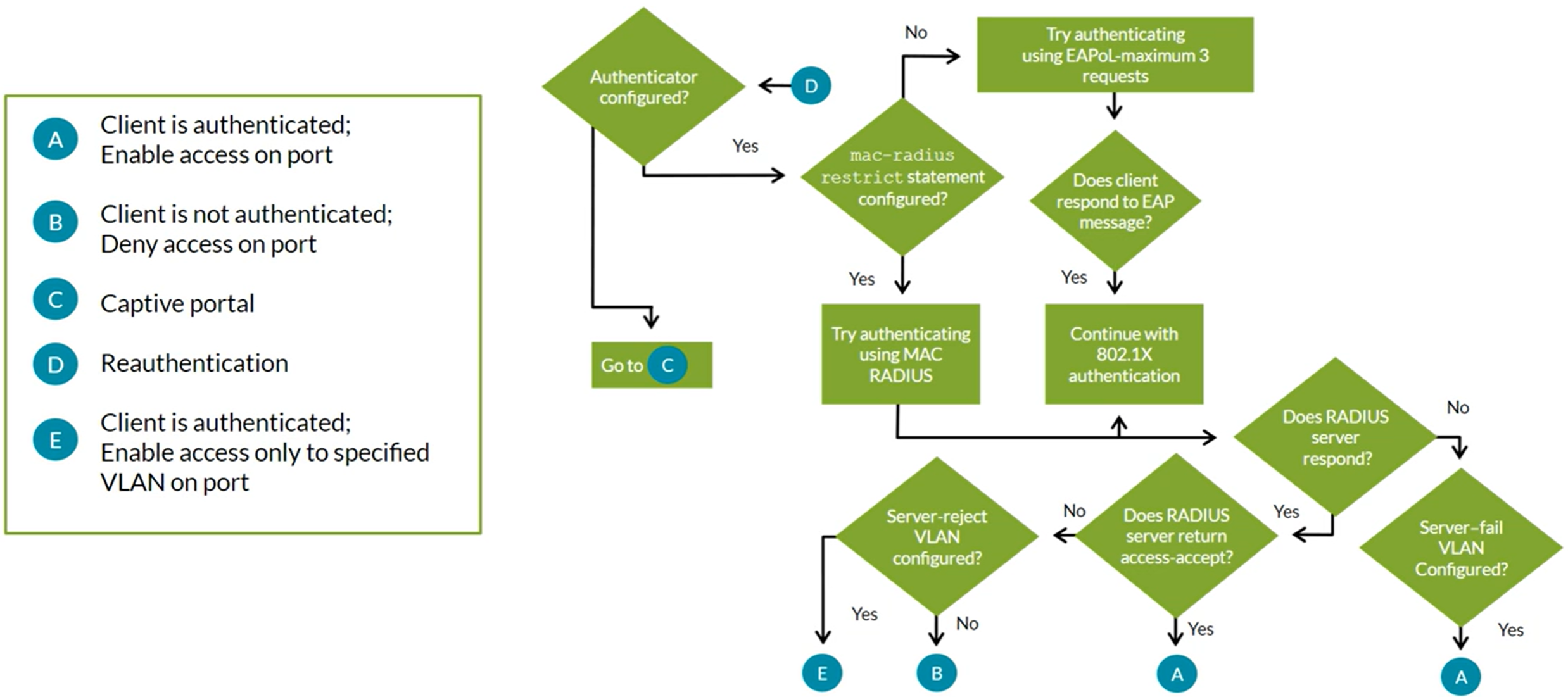
802.1X MAC Radius Captive Portal
Radius clients are network devices that rqeuest AAA services from a RADIUS server.
802.1X IEEE defines a method to authenticate and associate users with network access rights based on an assigned profile and VLAN.
Dynamic VLAN Assigment
802.1X can dynamically associate hosts with their corresponding VLANs during authentication process. RADIUS server returns VLAN attributes as part of the access-accept message (VLAN must be configured on the switch).
Guest VLAN
Provides limited access, typically just Internet access, for Guests and devices that don’t support 802.1X authentication
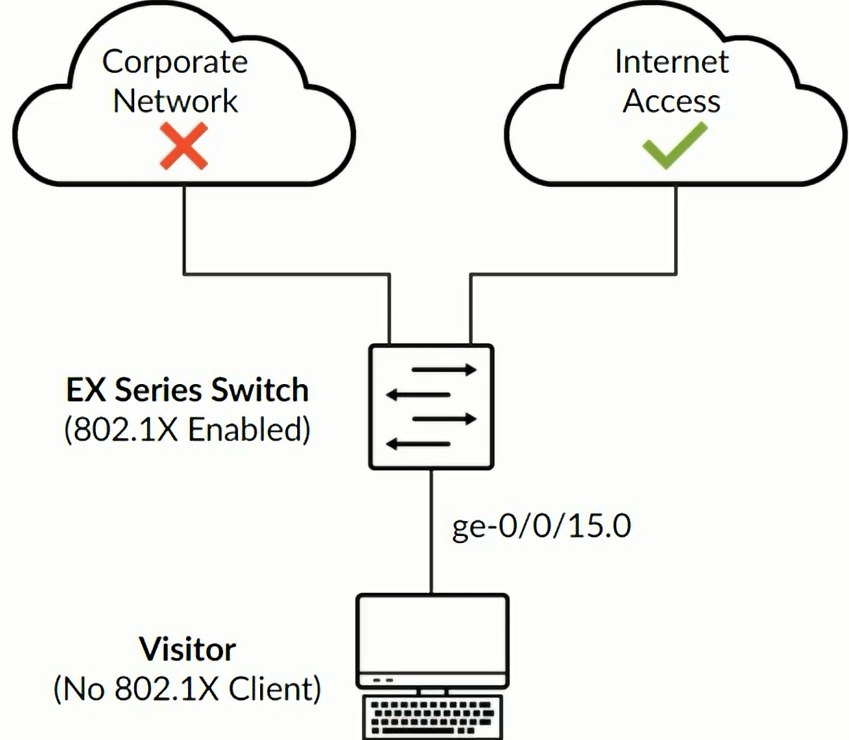
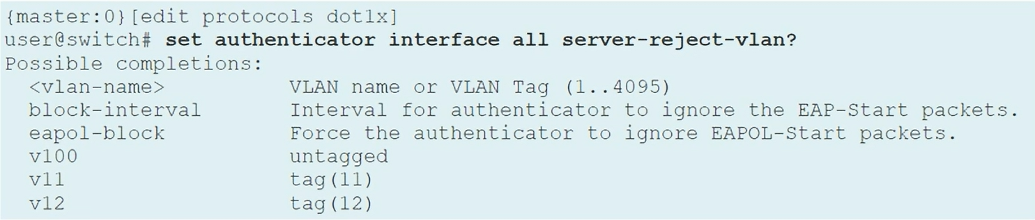
Suplicants can be moved to a specific VLAN upon the Authenticator receiving an access-reject message from the RADIUS Server.
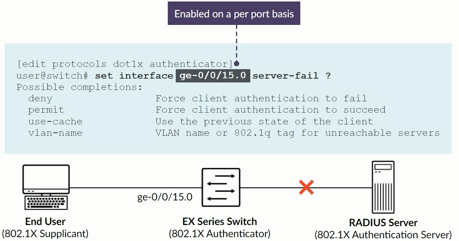
Server Fail Fallback Options
If RADIUS server fails to respond or authenticate a device, these are the supported actions:
- Permit: Enables traffic from devices as if they are successfully authenticated by the RADIUS server
- Deny: Prevents traffic from devices (default behavior)
- Move: Associates device with the specified VLAN
- Sustain: Maintains authentication for devices that already have LAN access and denies unauthenticated devices
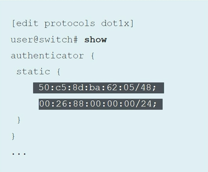
Static MAC Bypass
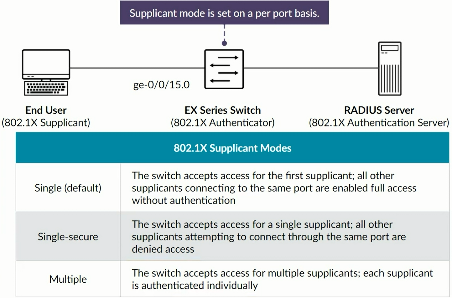
Exclusion list specifying MAC addresses of devices allowed access to the ALN without authentication. Commonly used with printers and IP phones. You must use the Multiple Supplicant mode.
Configuring 802.1X
Access Control Features - MAC Radius and Captive Portal
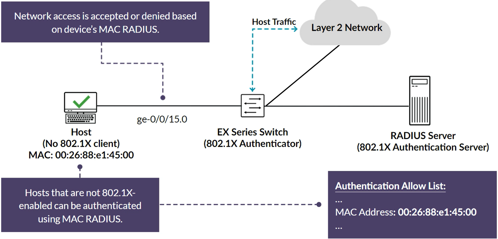
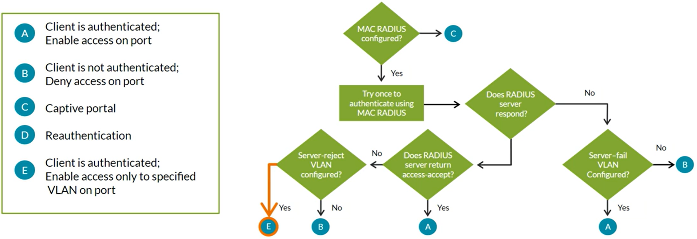
MAC RADIUS
Uses a centralized RADIUS Server and database to authenticate end user devices not 802.1X enabled. Hosts that are not 802.1X-enabled can be authenticated using MAC RADIUS.
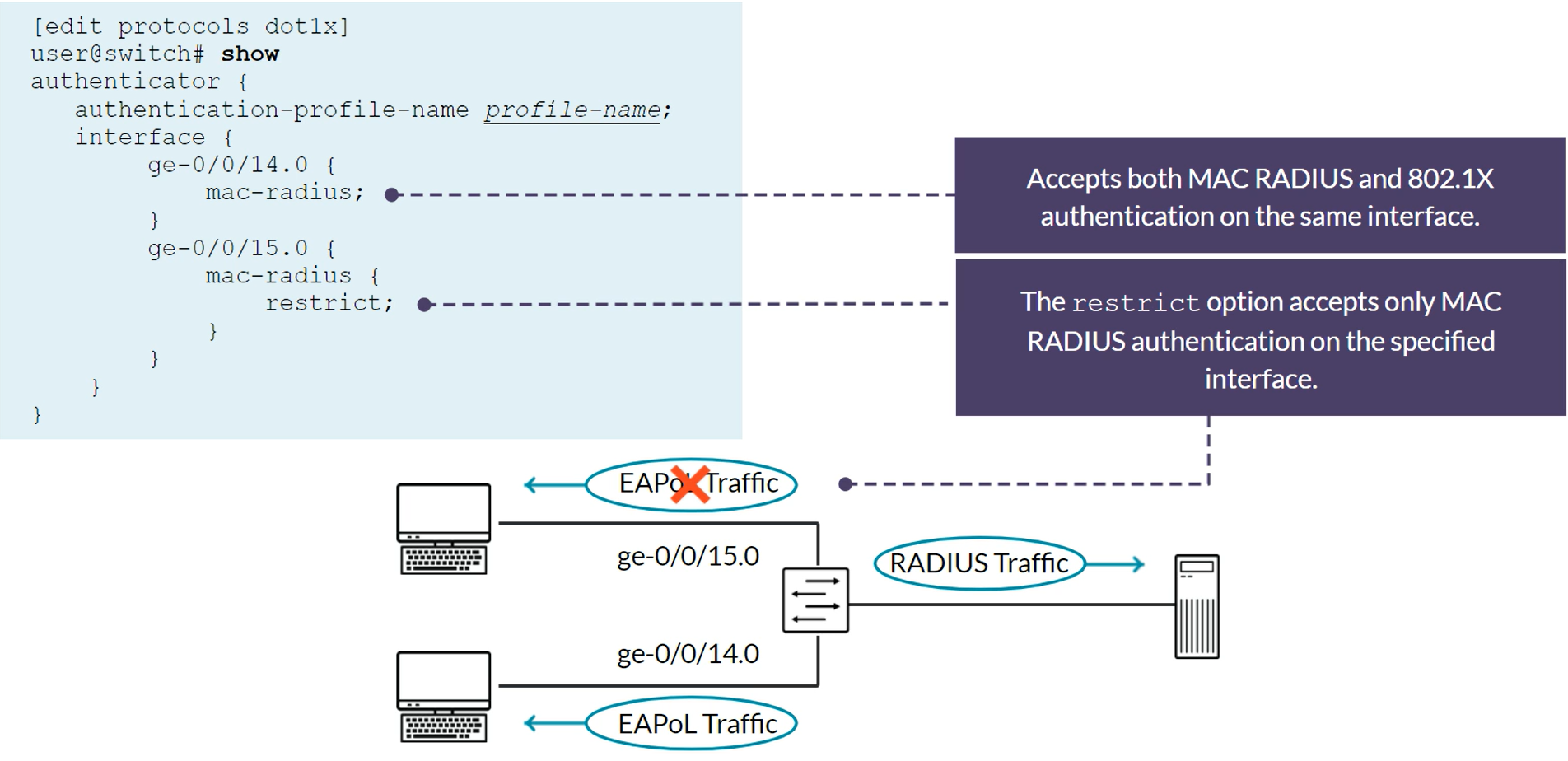
MAC RADIUS and 802.1X on the same port
- MAC RADIUS can be configured in conjuction with 802.1X on ports that also serve 802.1X clients
- The switch uses the Extensible Authentication Protocol-Message Digest 5 (EAP-MD5) method, when both 802.1X amd MAC RADIUS authentication methods are enabled on the same port
- With the preivuos case, if only non-802.1X-enabled end devices connect to a given interface, you can eliminate the delay (which can be upto 90 seconds) by configuring the
mac-radius restrictoption
Configuring MAC RADIUS
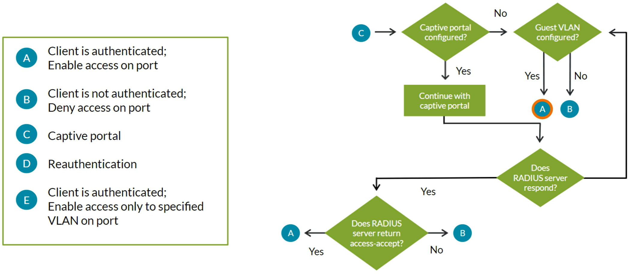
Captive Portal Access Control Features
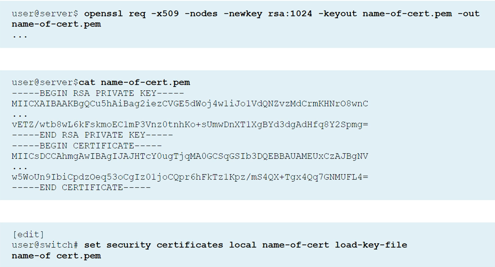
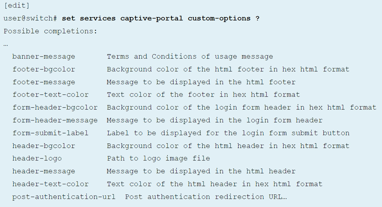
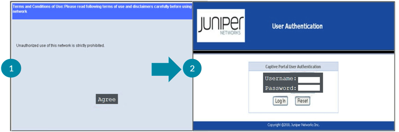
Uses authentication with RADIUS server. Captive Portal is enabled on individual interfaces on EX switches. Captive Portal can be configured on Layer 2 interfaces. Captive Portal does not support dynamic VLAN assigments through the RADIUS server. Captive Portal is a supported fallback option for 802.1X. By Default, Captive Portal uses the single supplicant mode. Captive Portal limits the number of user authentication attempts, the default is 3. After these attempts, the wait period to retry is 60 seconds by default. Upon expiry of the re-authentication timer, Captive Portal tears down the connection. Sessions by default are 3600 seconds (1 hour), which can be changed in the configuration per interface or for all the interfaces with the command “session expiry”. When an end-user device opens a Web browswer and points to a remote website, the connected switch, with the Captive Portal feature enabled, intercepts the request and presents the user with the Captive Portal login HTML page. The Captive Portal login HTML page requests the user’s username and password. End-device should have IP/Mask, Gateway, DNS information so DHCP & DNS traffic is bypassed.
Authentication Allowlist
This is just to bypass devices from the Captive Portal (printers, IP Phones, etc) by having their MAC address statically configured in a local list in the Switch’s configuration.
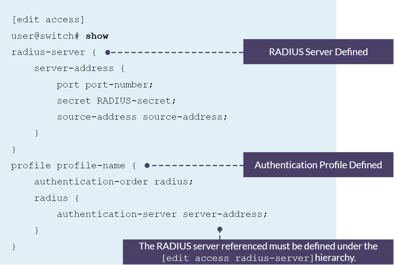
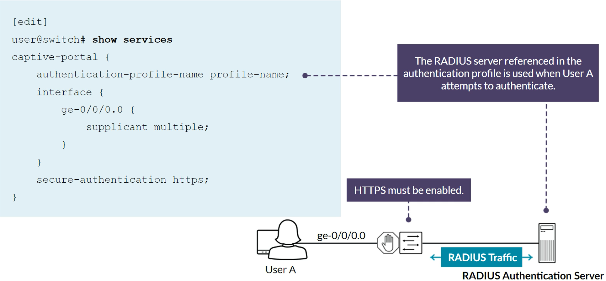
Captive Portal configuration
Captive Portal Authentication Allowlist configuration
NOTE: Multiple supplicant must is required.
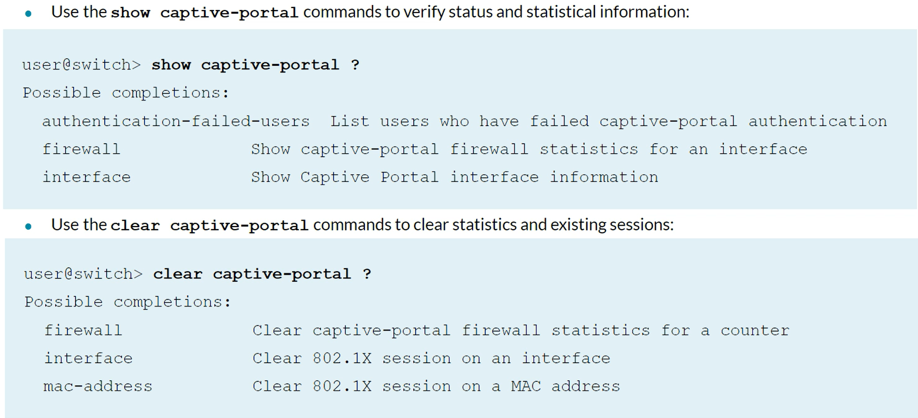
Captive Portal verification
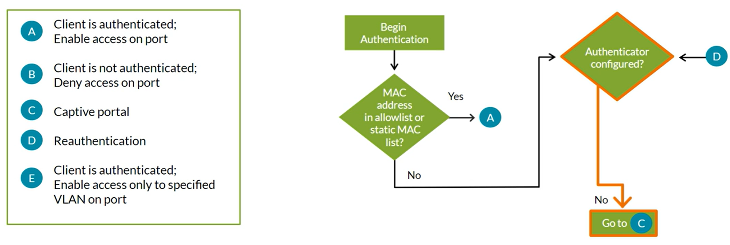
Authentication Process Considerations
Listing all authentication processes here:
- 802.1X
- MAC RADIUS
- Captive Portal
- MAC Allowlist & Static MAC Bypass
- Server-Reject VLAN & Guest VLAN
Captive Portal cannot be mixed for active authentications with 802.1X and/or MAC Radius.
Fallback order:
- 802.1X Authentication
- MAC RADIUS Authentication
- Captive Portal Authentication
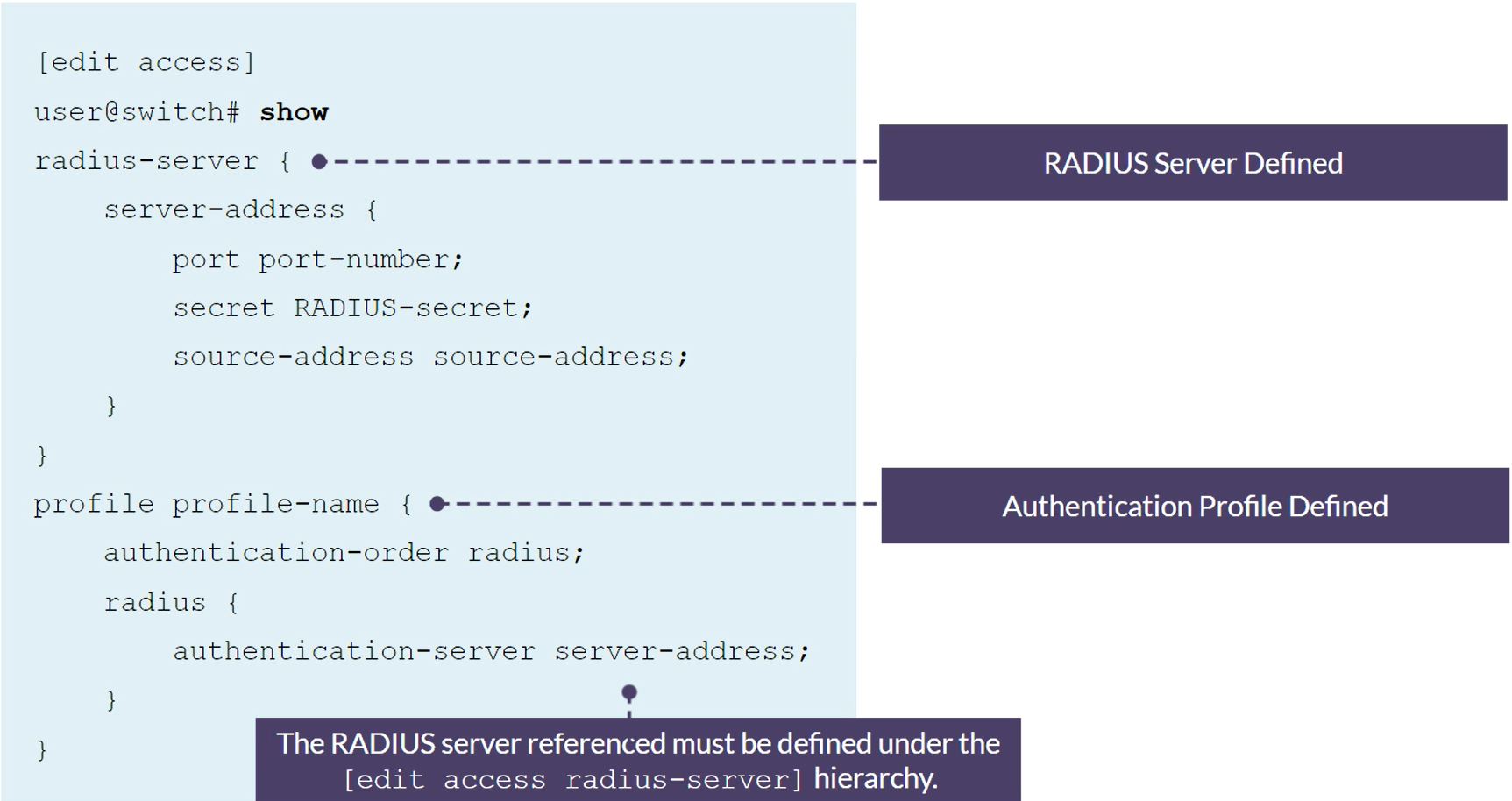
Configuring 802.1X
1
2
3
4
5
6
7
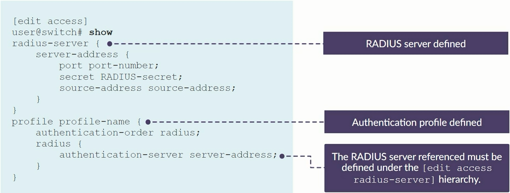
set access radius-server 172.25.11.254 secret Juniper
set access profile my-profile authentication-order radius
set access profile my-profile radius authentication-server 172.25.11.254
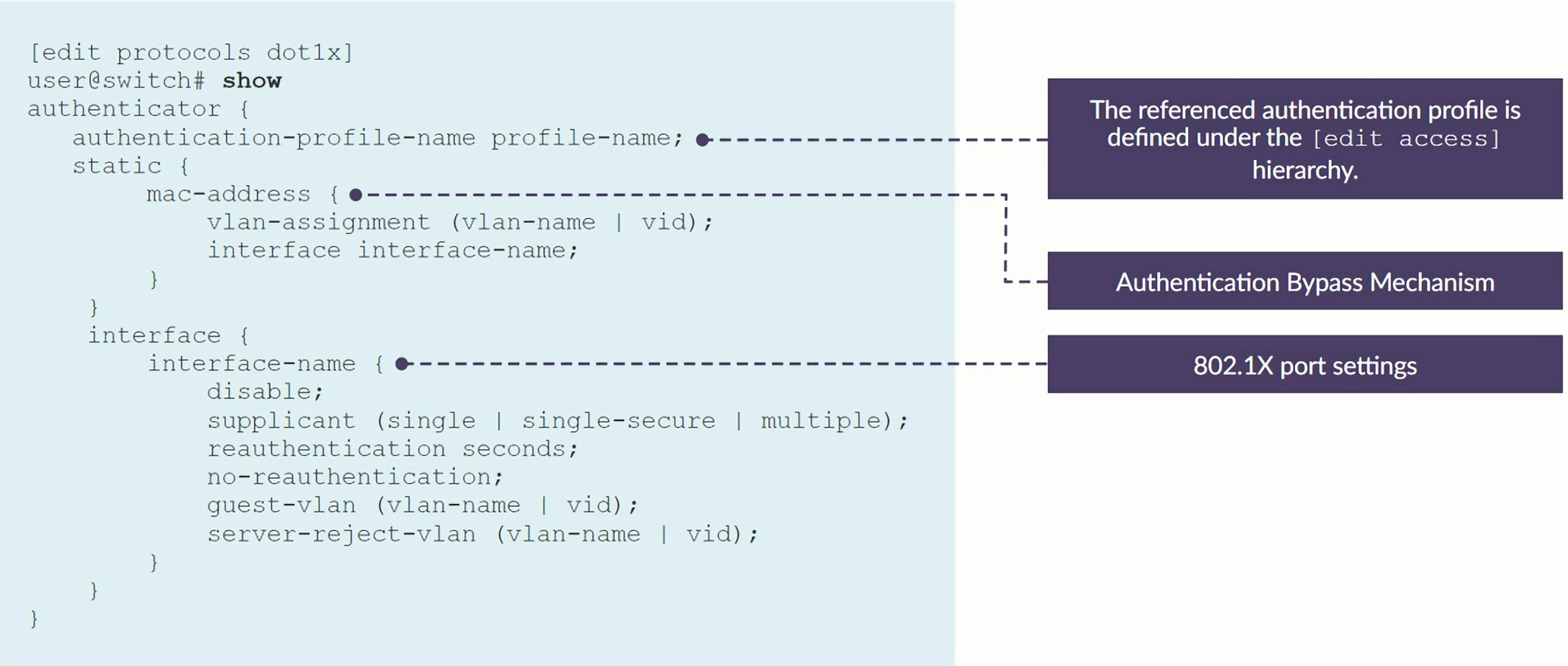
set protocols dot1x authenticator authentication-profile-name my-profile
set protocols dot1x authenticator interface ge-0/0/10
set protocols dot1x authenticator interface ge-0/0/12
Single-secure suplicant mode
1
2
3
set protocols dot1x authenticator interface ge-0/0/10 no-reauthentication # Disabling re-authentication
set protocols dot1x authenticator interface ge-0/0/12 suplicant single-secure # By default suplicant mode is "Single", we're changing that on this line
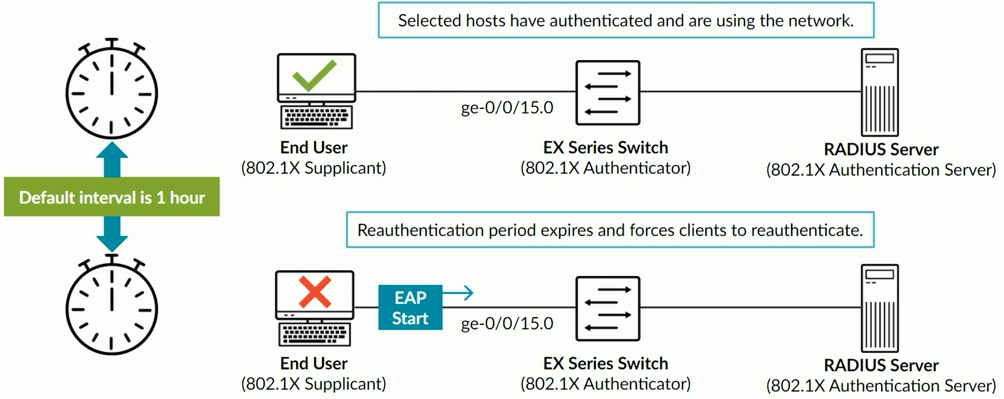
set protocols dot1x authenticator interface ge-0/0/12 reauthentication 7200 # By default it is 3600 (1 hour)
MAC Bypass
1
set protocols dot1x authenticator static 00:26:88:00:00:00/24
Multiple suplicant mode
1
2
set protocols dot1x authenticator interface ge-0/0/10 suplicant multiple
set protocols dot1x authenticator interface ge-0/0/12 suplicant multiple
MAC RADIUS
1
2
set protocols dot1x authenticator interface ge-0/0/10 mac-radius restrict
set protocols dot1x authenticator interface ge-0/0/12 mac-radius restrict
Fail fallback - allows traffic on port even when RADIUS was unresponsive to the request
1
2
set protocols dot1x authenticator interface ge-0/0/10 server-fail permit
set protocols dot1x authenticator interface ge-0/0/12 server-fail permit
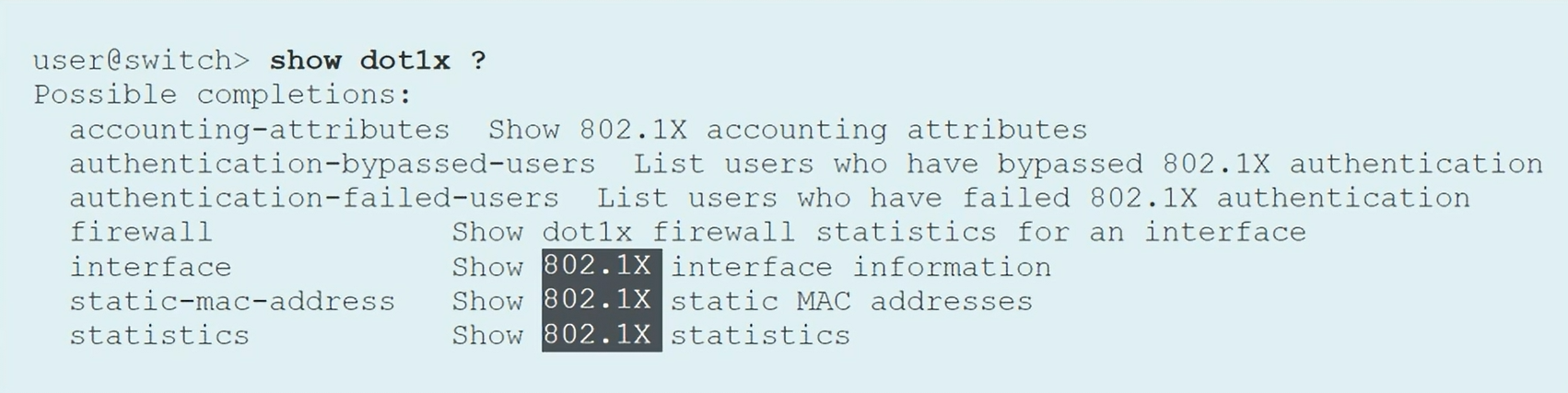
Commands to verify the configuration
1
2
3
4
show dot1x interface
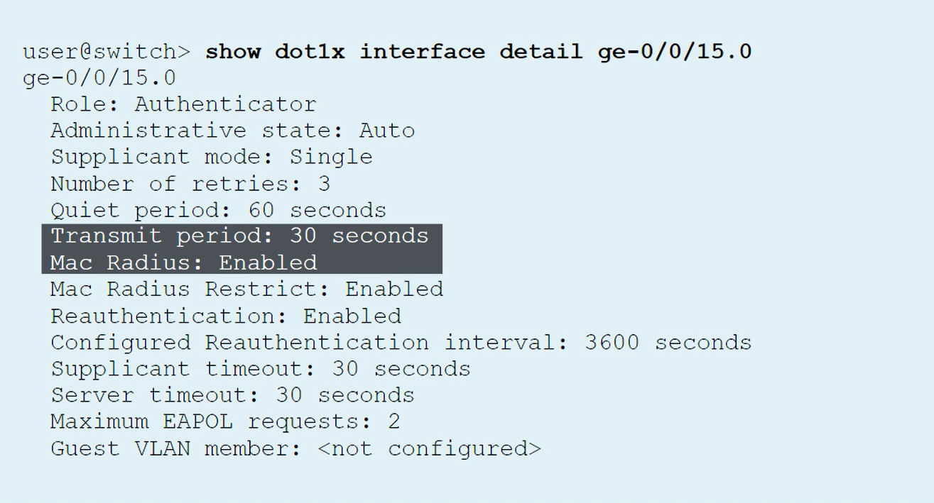
show dot1x interface detail
show dot1x interface ge-0/0/10 detail
show dot1x static-mac-address
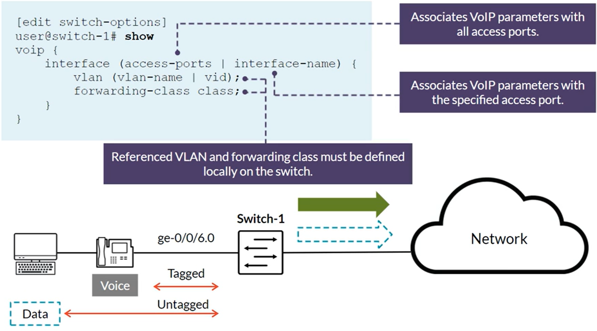
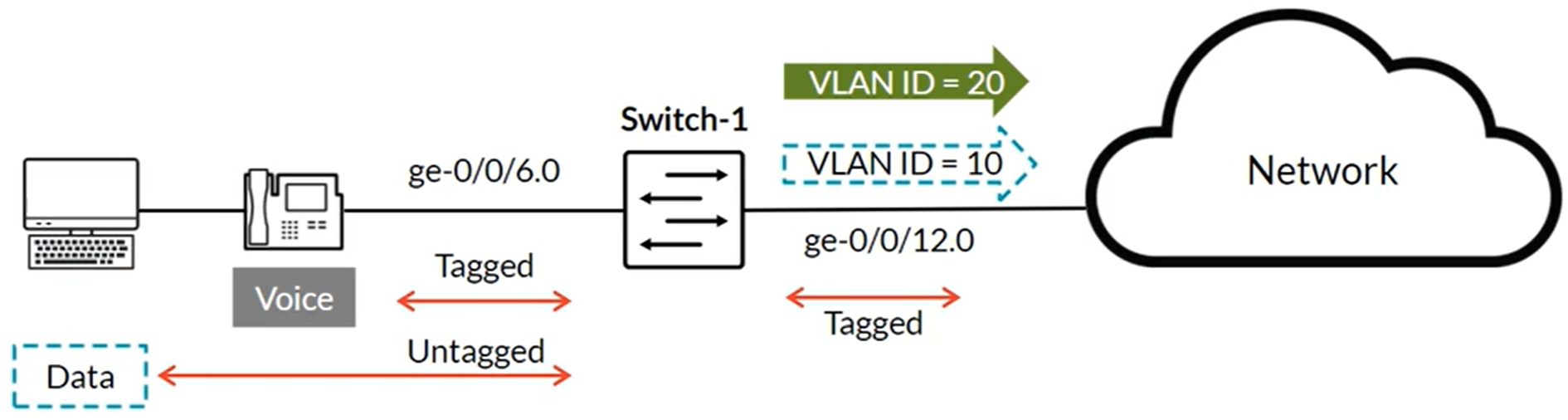
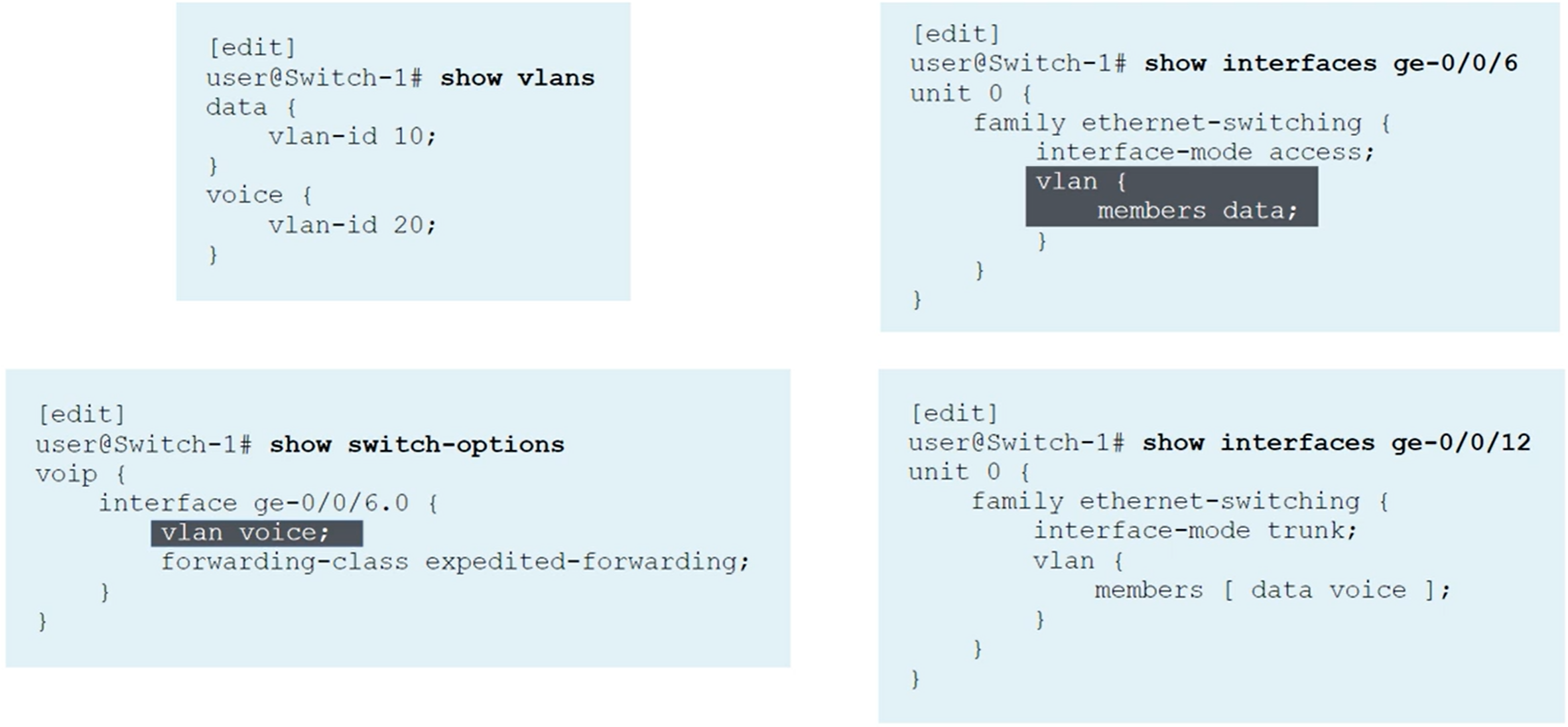
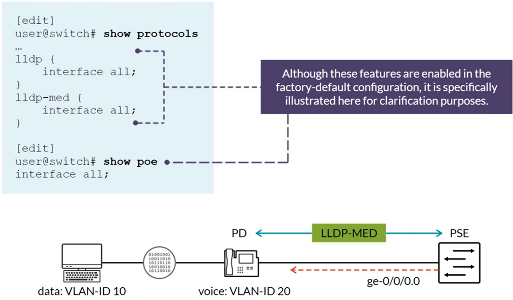
IP Telephony Features: Voice VLAN
The voice VLAN feature enables access ports to accept both untagged (data) and tagged (voice) traffic and separate that traffic into different VLANs. Used with the class of service (CoS) to differentiate data and voice traffic Voice VLAN and CoS values can be communicated to IP phones through LLDP-MED (Link Layer Discovery Protocol-Media Endpoint Discovery).
Commands to verify
1
2
show lldp local-information
show lldp statistics interface ge-0/0/10
L3 port with 802.1Q / VLAN tagging
1
2
3
4
set interfaces ge-0/0/11 vlan-tagging
deactivate interfaces ge-0/0/11 unit 0
set interfaces ge-0/0/11 unit 25 vlan-id 25
set interfaces ge-0/0/11 unit 25 family inet addresss 172.23.25.11/24
Capture traffic on an interface
1
monitor traffic interface ge-0/0/10 print-ascii no-resolve detail
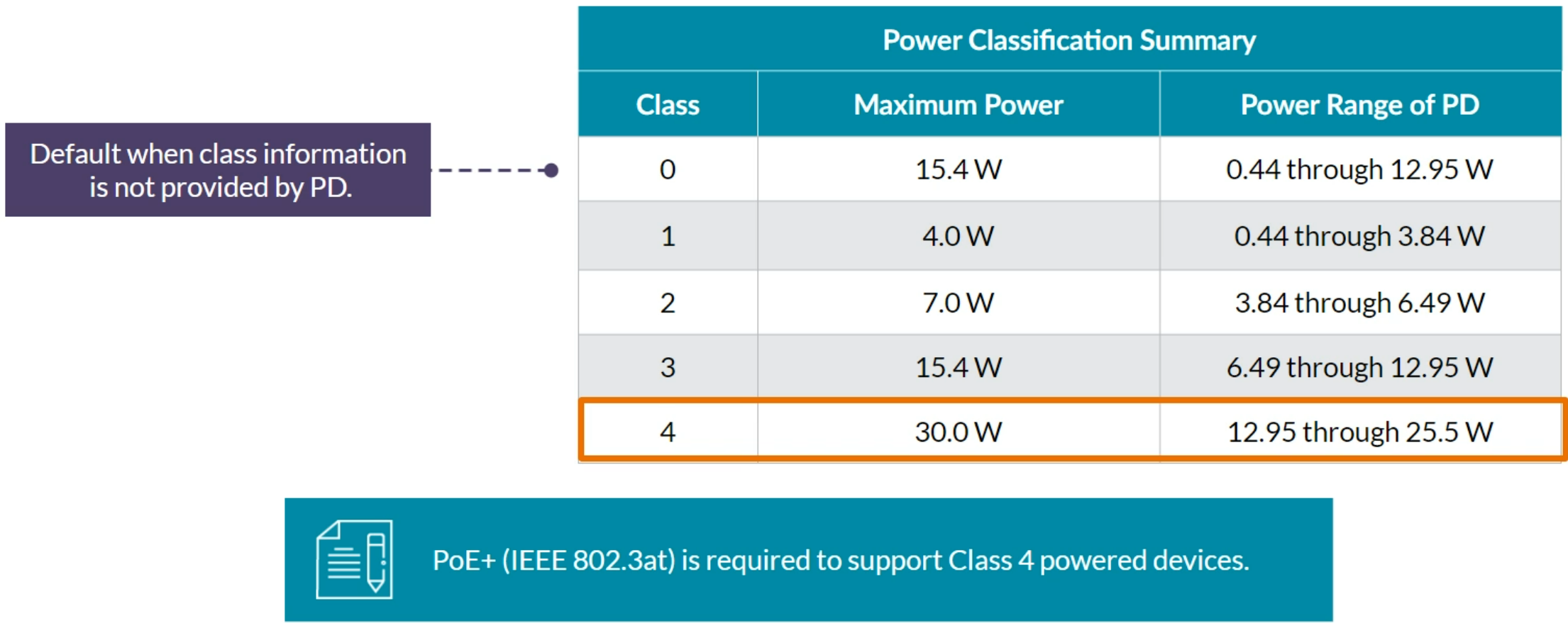
IP Telephony Features: Power over Ethernet and Neighbor Discovery using LLDP
Power over Ethernet Plus (PoE+) was designed to support PDs with higher power level requirements.
- PoE (IEEE 802.3af) provides up to 15.4W of power
- PoE (IEEE 802.3at) provides up to 30W of power
Configuring PoE
PoE Verification Commands
1
2
3
show chassis hardware
show poe interface
show poe interface ge-0/0/0
When 802.1X is enabled, LLDP frames are not transmitted or received until the port is authenticated.
When an IP Phone and a PC both connected to the same 802.1X enabled port and only one of them is configured to be 802.1X supplicant, use the Single supplicate mode on the Switch’s port. When both are configured as 802.1X supplicant use the Multiple supplicant mode.
Configuring LLDP
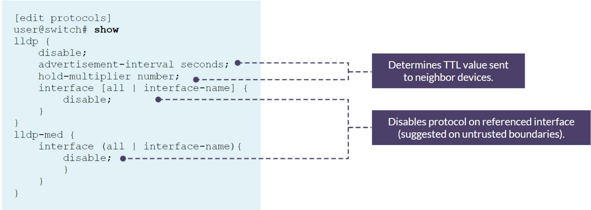
Verification commands
1
2
3
4
show lldp detail
show lldp neighbors
show lldp local-info
show lldp statistics
Class of Service
- Policers monitor and limit traffic on ingress interfaces
- Shapers monitor and limit traffic on egress interfaces or queues
- Port shaping defines the maximum bandwidth allocated to a port
- Queue shaping defines a limit at which queues transmit packets
1
set class-of-service code-point-aliases dscp custom-ef 101110
1
2
3
4
show class-of-service interface ge-0/0/6
show class-of-service code-point-aliases
show class-of-service forwarding-class
show interfaces ge-0/0/16 extensive
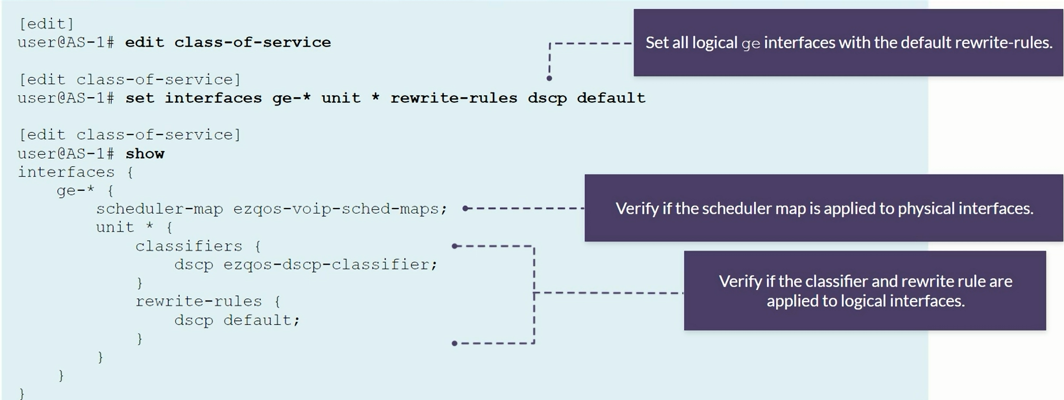
Rewrite rules are applied to logical interfaces
1
2
show class-of-service rewrite-rule type dscp
set interfaces ge-* unit * rewrite-rules dscp
Changing the Default behavior on EX Switches
The default behavior is overwritting the CoS fields, so in case the EX switch receives a frame with the CoS set to EF, the frame will be allocated to Queue 0 and forwarded with CoS all zeros.
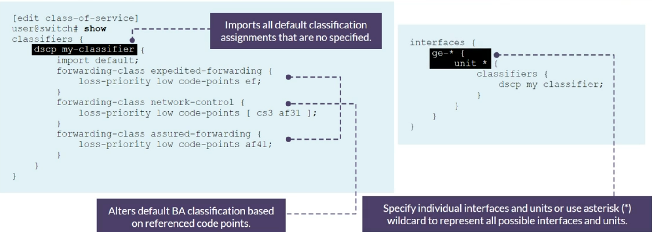
Enabling Behavior Aggregate (BA)
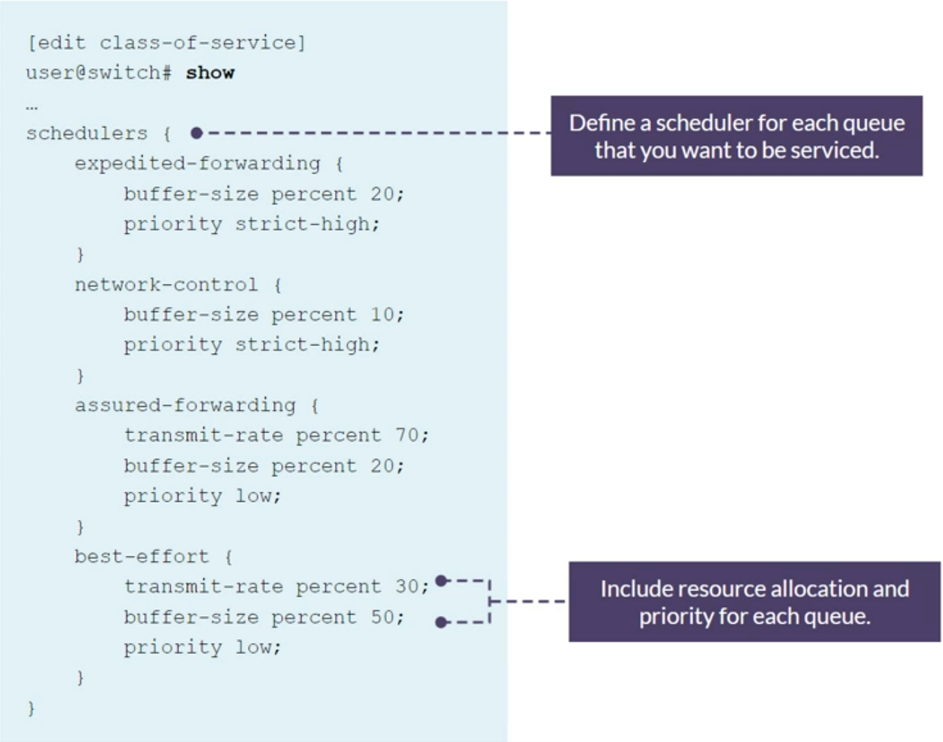
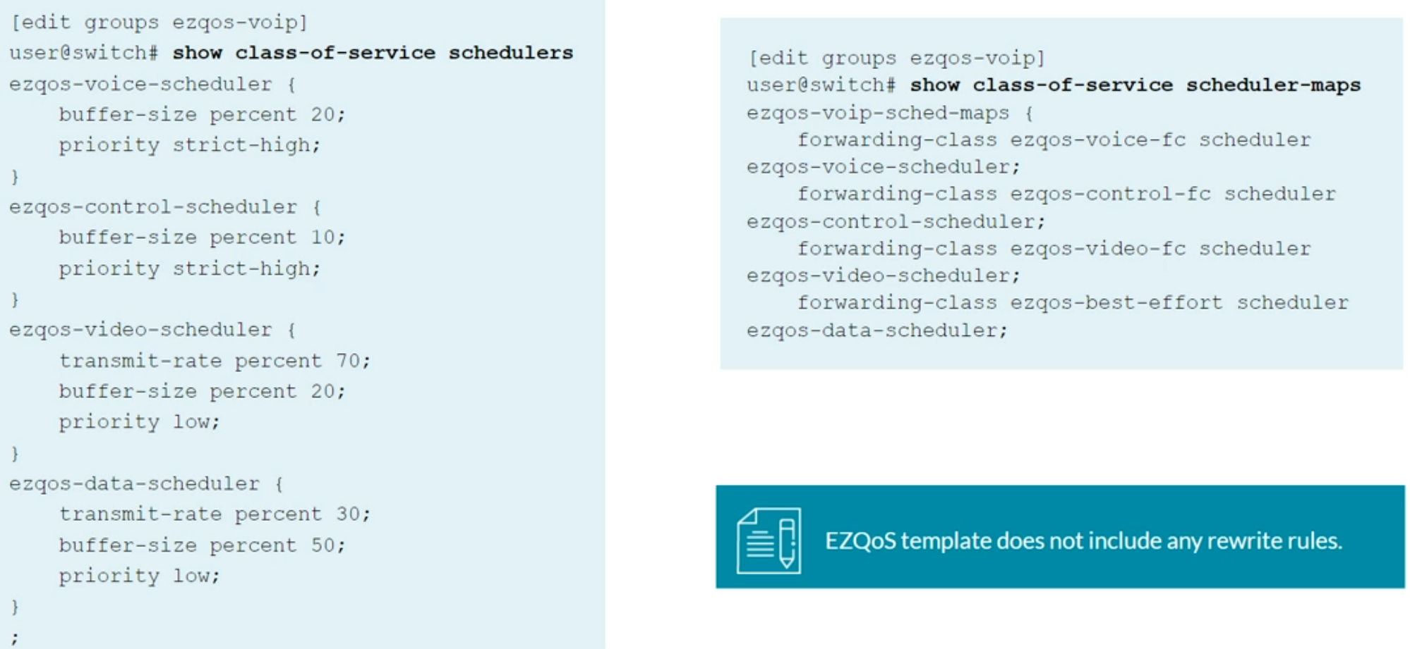
Defining Schedulers
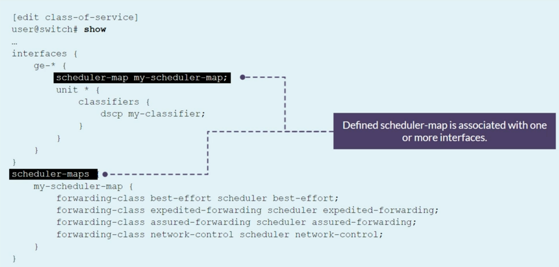
Configuring Schedulers Maps
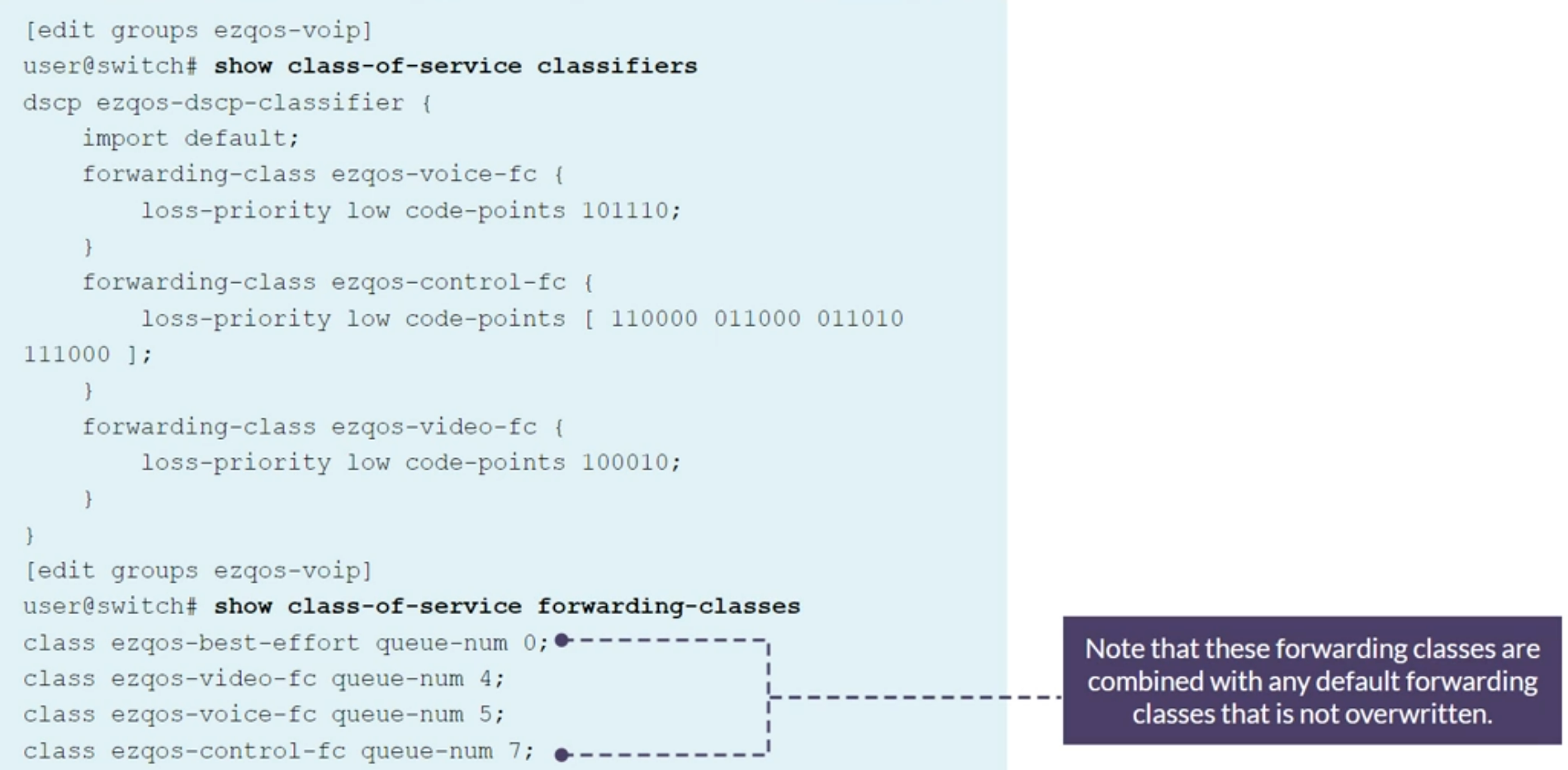
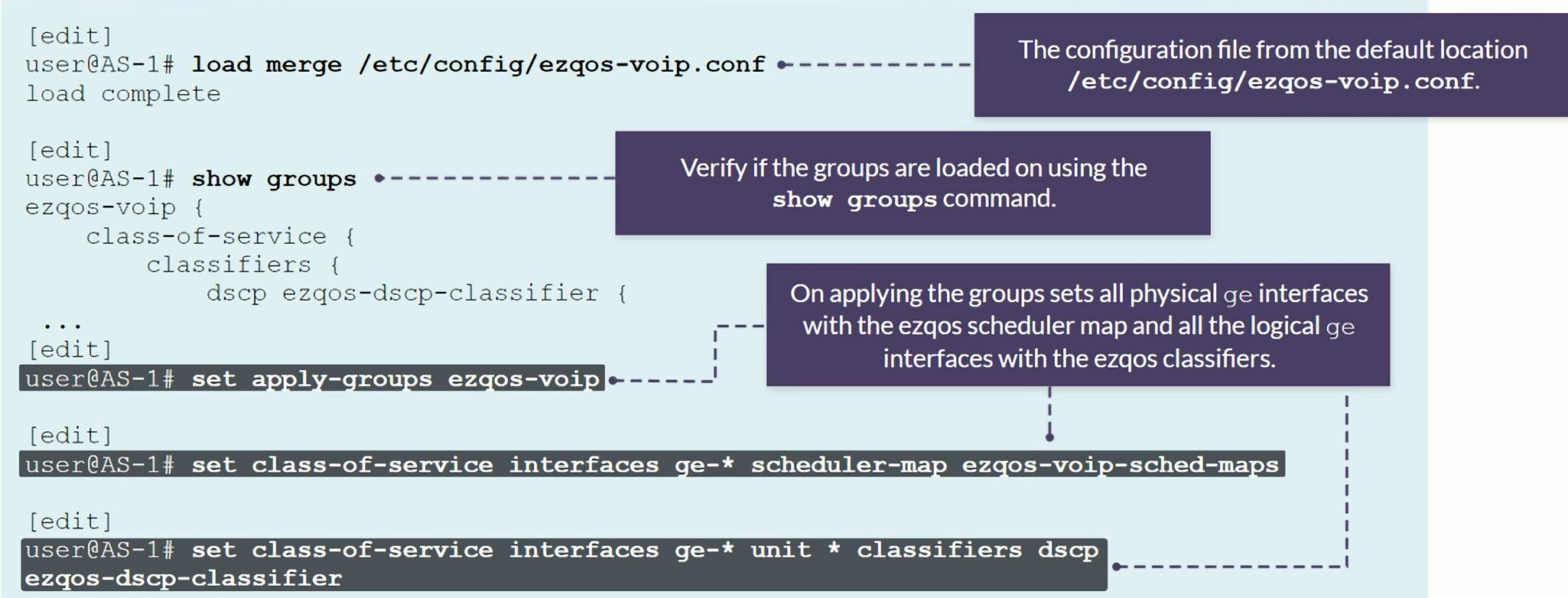
EZQoS configuration template
Template specifically designed for VoIP deployments
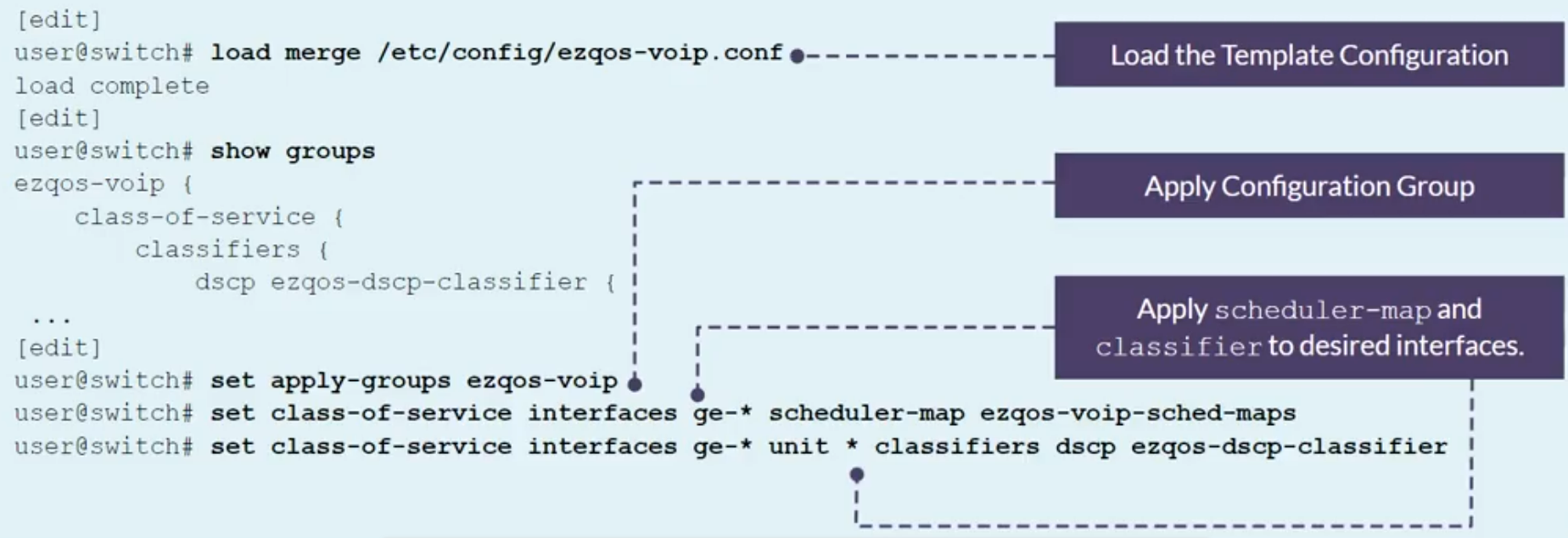
Class of Service Implementation
- Use EZQoS template to consistently implement class of service (CoS)
- Use operational mode commands to verify proper operations.
1
2
3
4
5
6
7
8
show class-of-service code-point-aliases dscp | match ef
show class-of-service forwarding-class
show class-of-service classifier name ezqos-dscp-classifier
show class-of-service interface ge-0/0/6
show interfaces ge-0/0/10 extensive | find "Queue counters"
show interfaces ge-0/0/10 extensive | find "CoS information"
show interfaces queue ge-0/0/10 egress
traceroute x.x.x.x tos 0
| command | description |
|---|---|
| show interfaces extensive | Show interface statistics and Packet Forwarding Engine queue configuration |
| show interface queue | Show detailed per-queue interface statistics |
| show class-of-service interface | Display every CoS-related feature active on the interface |
| traceroute | Can help for a summary checking of rewrite rules |
| show firewall | Defines counters on multifield classifiers at the edge or forwarding classes in the core-is a valuable troubleshooting tool |
Network Troubleshooting
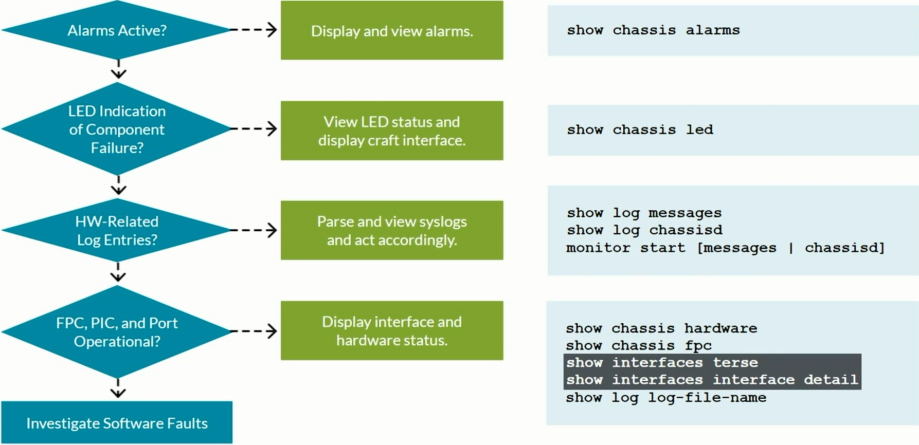
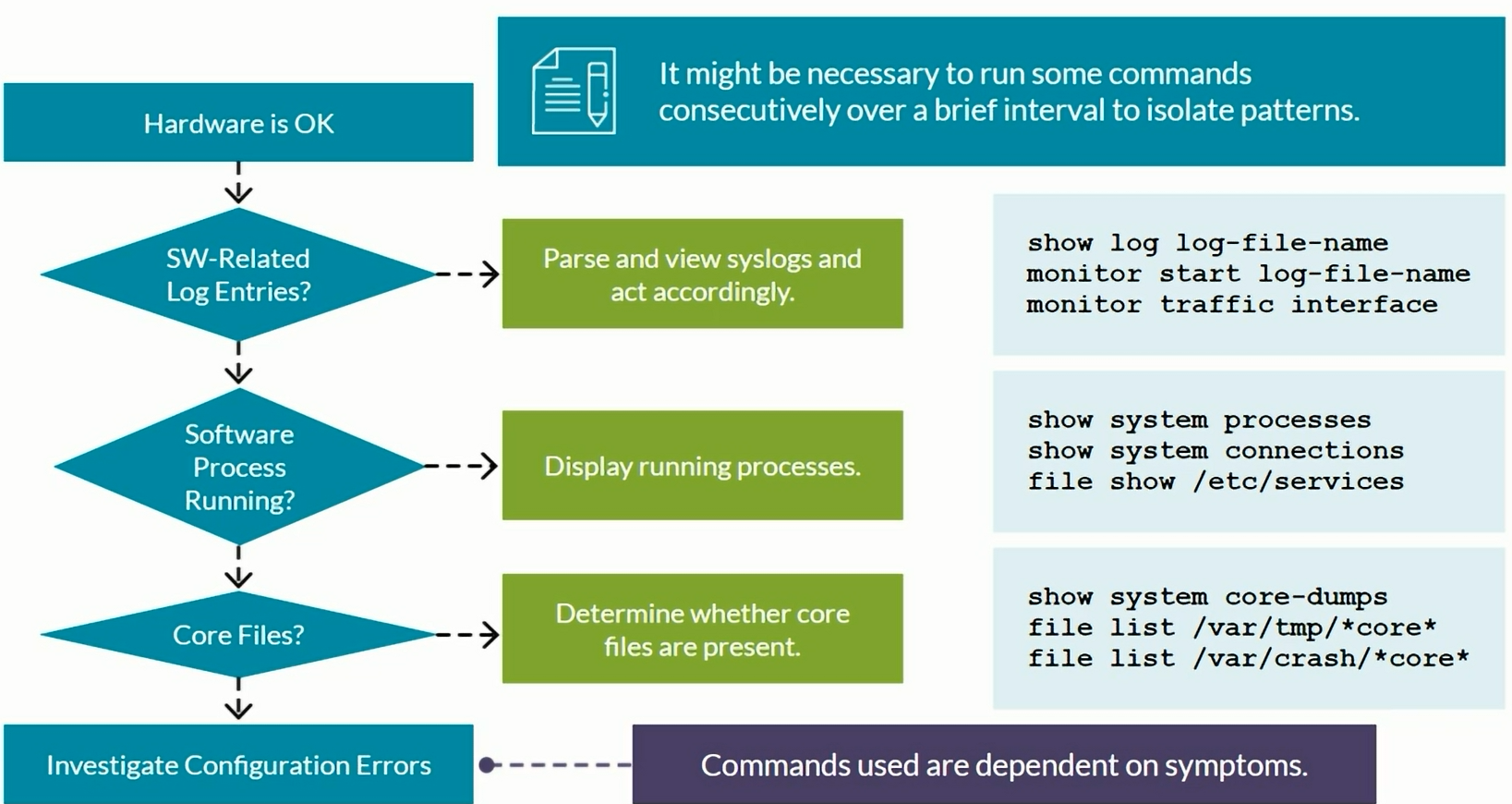
Hardware troubleshooting
System log
1
2
set system syslog file messages any notice
set system syslog file messages authorization info
Traceoptions
1
2
set protocols rstp traceoptions file rstp-trace-file
set protocols rstp traceoptions flag all-failures
Routing Engine
1
show chassis routing-engine
Process Failures
1
show system core-dumps
JTAC usually request these outputs
1
2
3
4
5
set cli timestamp

request support information | no-more
show log messages
show log chassisd
Network Troubleshooting tools
SNMP
1
set snmp health-monitor ?
sFlow
1
2
3
4
5
6
set protocols sflow polling-interval 20
set protocols sflow sample-rate egress 100
set protocols sflow source-ip <management-address>
set protocols sflow collector 10.10.10.254 udp-port 6343
set protocols sflow interfaces ge-0/0/10.0
set protocols sflow interfaces ge-0/0/12.0
1
2
show sflow
show sflow collector
Port Mirroring
1
2
3
set forwarding-options analyzer monitor-AB input ingress interface ge-0/0/0.0
set forwarding-options analyzer monitor-AB input ingress interface ge-0/0/1.0
set forwarding-options analyzer monitor-AB output interface ge-0/0/10.0
1
monitor interface traffic
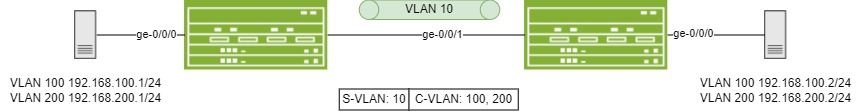
Q-in-Q configuration example
1
2
3
4
5
6
7
8
9
10
11
12
13
14
15
16
17
18
19
20
21
22
23
24
25
root@switch> show configuration interfaces
ge-0/0/0 {
    flexible-vlan-tagging;
    encapsulation extended-vlan-bridge;
    unit 10 {                        <<<< Defines outer tag or Service VLAN tag.
        vlan-id-list [ 100 200 ];    <<<< Defines inner tags or customer VLAN tags.
        input-vlan-map push;         <<<< Pushes tag 10 on top of 100 OR 200.
        output-vlan-map pop;         <<<< Pops tag 10 leaving only tag 100 OR 200.
    }
}
ge-0/0/1 {
    flexible-vlan-tagging;
    mtu 1522;
    encapsulation flexible-ethernet-services;
    unit 10 {
        encapsulation vlan-bridge;
        vlan-id 10;
    }
}

root@switch> show configuration vlans
QinQ-Tunnel {
    interface ge-0/0/0.10;
    interface ge-0/0/1.10;
}
[EX] Understanding and configuring 802.1Q (Q-in-Q) dot1q tunneling with examples
MSTP config and output examples
EX Switch A Configuration:
1
2
3
4
5
6
7
8
9
10
11
12
13
14
15
16
[Edit protocols mstp]
user@switchA# show
  configuration-name test >>>>> Must Match on participating switches. - User defined configuration name.
  revision-level 1;       >>>>> Must Match on participating switches.
  msti 1 {
    bridge-priority 4k;
    vlan 1-10;            >>>>> Must Match on participating switches.
  }
  msti 2 {
    bridge-priority 8K;   >>>>> MSTP instances defined with individual bridge-priority values and VLAN ranges
    vlan 11-20;
  }
  msti 3 {
    bridge-priority 12k;
    vlan 21-30;
  }
EX Switch B Configuration:
1
2
3
4
5
6
7
8
9
10
11
12
13
14
15
16
[Edit protocols mstp]
user@switchA# show
  configuration-name test >>>>> Must Match on participating switches. - User defined configuration name.
  revision-level 1;       >>>>> Must Match on participating switches.
  msti 1 {
    bridge-priority 12k;
    vlan 1-10;            >>>>> Must Match on participating switches.
  }
  msti 2 {
    bridge-priority 4K;   >>>>> MSTP instances defined with individual bridge-priority values and VLAN ranges
    vlan 11-20;
  }
  msti 3 {
    bridge-priority 8k;
    vlan 21-30;
  }
Verifying MST activity on the EX Switch:
1
2
3
4
5
6
7
8
9
10
11
12
user@switchA# run show spanning-tree mstp configuration
MSTP information
Context identifier     : 0
Region name            : test
Revision               : 10
Configuration digest   : 0x476c7ee38f56eea4a9bbe3fa9e7b7979

MSTI     Member VLANs
   0 0,31-4094
   1 1-10
   2 11-20
   3 21-30
EX-series Switch and MSTP (Multiple Spanning Tree Protocol)
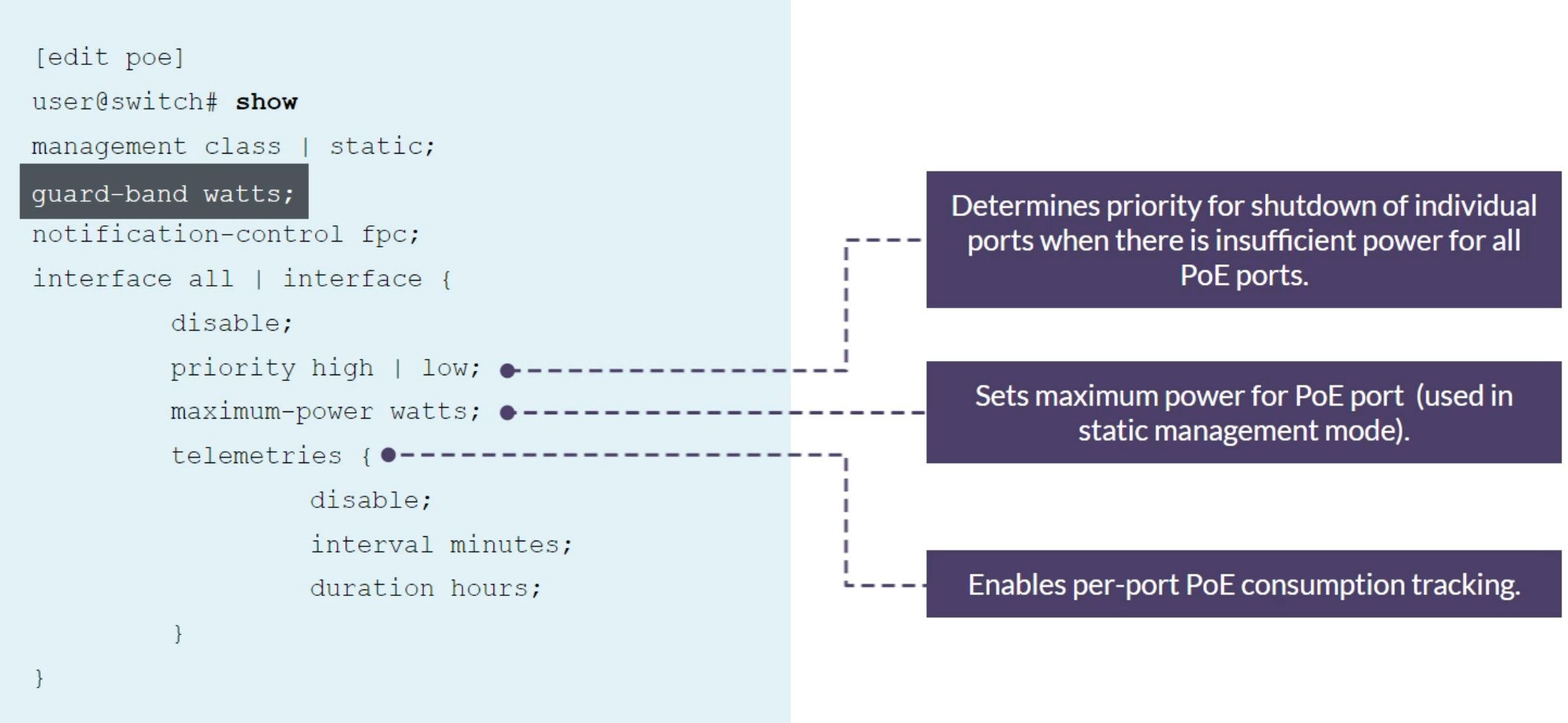
PoE priority
Set the power priority for individual interfaces when there is insufficient power for all PoE interfaces. If the switch needs to shut down powered devices because PoE demand exceeds the PoE budget, low-priority devices are shut down before high-priority devices. Among interfaces that have the same assigned priority, priority is determined by port number, with lower-numbered ports having higher priority.
Junos CLI Reference - priority (Power over Ethernet)
CoS
- Behavior Aggregate Classifiers - core devices that handle high traffic volumes are normally configured to perform BA classification
- Multifield Classifiers - normally performed at the network edge because of the general lack of support for DSCP or IP precedence classifiers in end-user applications.
Understanding CoS Classifiers [EX] Full CoS Configuring with BA and MF classifier on Juniper Networks ELS switches except QFX5K and EX46’s