AWS Configure Site-to-Site VPN with GNS3
NOTE: All configurations were taken from a lab environment.
This post explains step by step the configuration of a Site-to-Site VPN between AWS and a virtual Router running in GNS3 in my personal laptop.
NOTE For this to work, the NAT-T feature is required to be enabled on your Home modem.
Overall, these are the steps:
- Step 1 - AWS : Configure a Customer Gateway (CGW)
- Step 2 - AWS : Configure a Virtual Private Gateway (VGW)
- Step 3 - AWS : Attach the VGW to a VPC
- Step 4 - AWS : Configure a Site-to-Site VPN connection
- Step 5 - AWS : Propagate the Routes in the Route Table
- Step 6 - GNS3 : Conect Router to the Internet
- Step 7 - GNS3 : Configure Router
- Step 8 - Validate connectivity using ICMP packets (ping test)
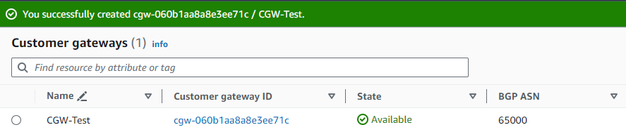
Step 1 - AWS : Configure a Customer Gateway (CGW)
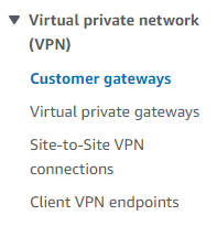
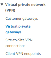
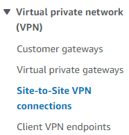
In the VPC section, go to Virtual private network (VPN) > Customer gateways
Click on orange button Create customer gateway on the upper-right part of the screen.
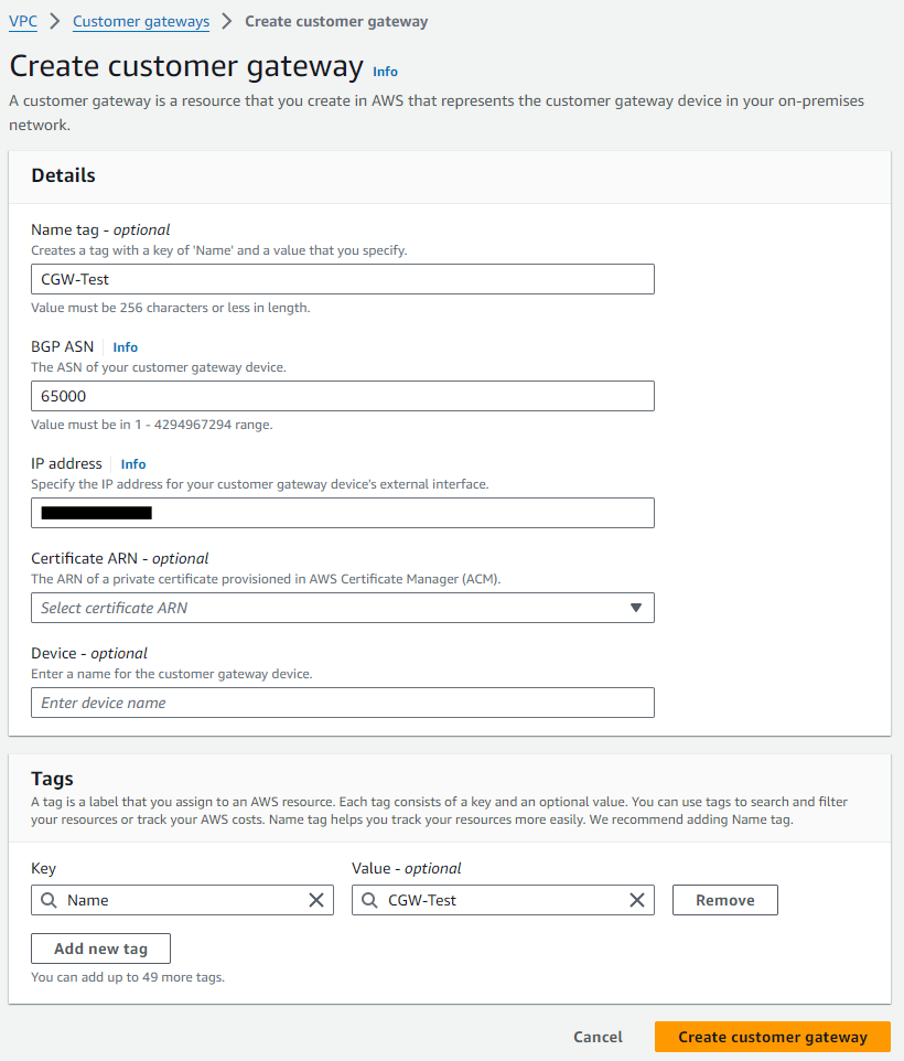
- NOTE: Obtain your Public IPv4 address from https://whatismyipaddress.com/
Step 2 - AWS : Configure a Virtual Private Gateway (VGW)
Still in the VPC section, go to Virtual private network (VPN) > Virtual private gateways
Click on orange button Create virtual private gateway on the upper-right part of the screen.
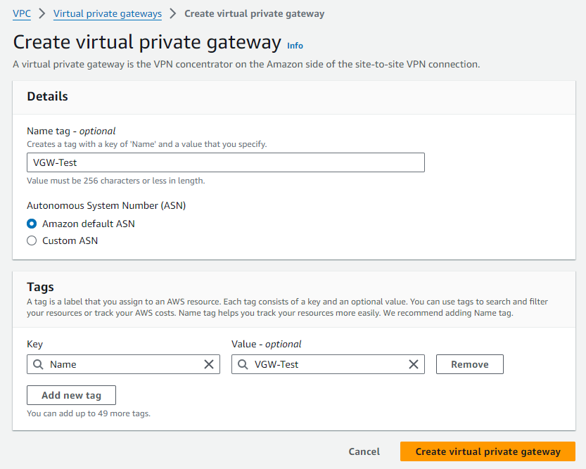
- NOTE: The Amazon default ASN is 64512
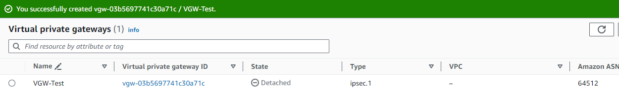
Step 3 - AWS : Attach the VGW to a VPC
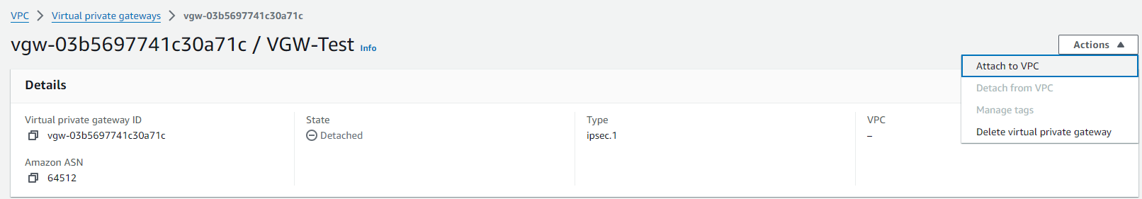
While still in Virtual private network (VPN) > Virtual private gateways, click on the newly created VGW
On the upper-right side of the screen, click on Actions > Attach to VPC
And select the desired VPC from the list of Available VPCs. In this case I am choosing the Default VPC
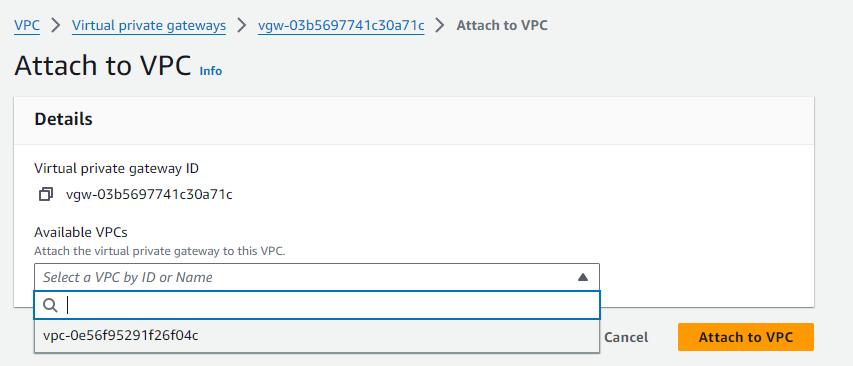
Finally, click on Attach to VPC.
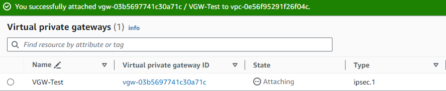
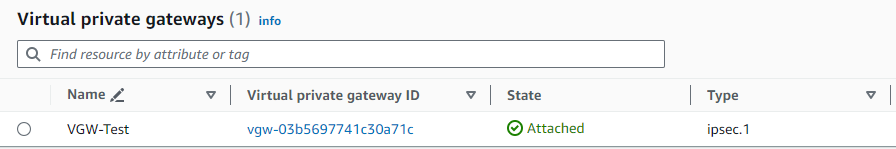
It should take a moment for the process to complete. You need to refresh the screen and see the State column showing Attached
Step 4 - AWS : Configure a Site-to-Site VPN connection
Go next to Virtual private network (VPN) > Site-to-Site VPN connections
Click on orange button Create VPN connection on the upper-right part of the screen.
Select the Virtual Private Gateway (VGW) and Customer Gateway (CGW) created previously.
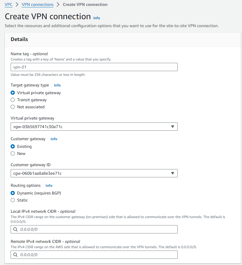
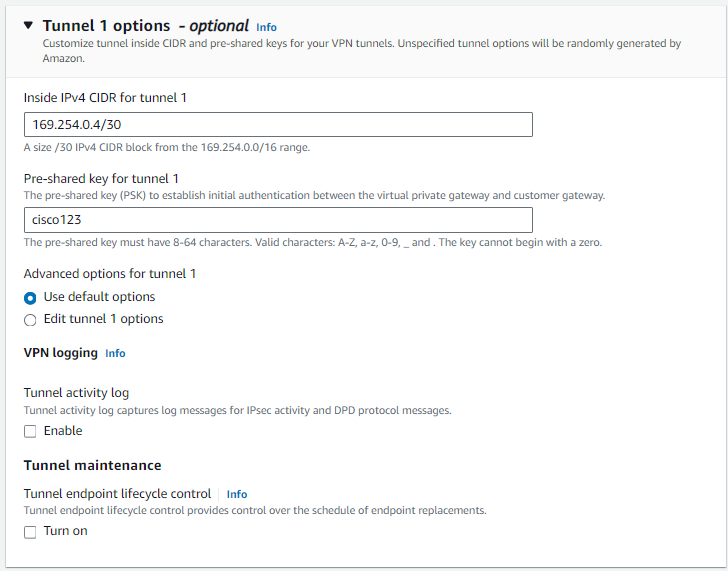
We are also adding an Inside IPv4 CIDR which is the Tunnel Point-to-Point IP addressing and Pre-shared key. These are optional but we are using them here to make the template configuration for the Cisco Router easier to read.
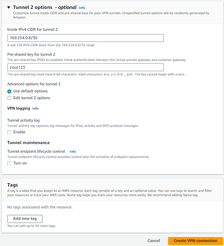
Click on the orange button Create VPN connection
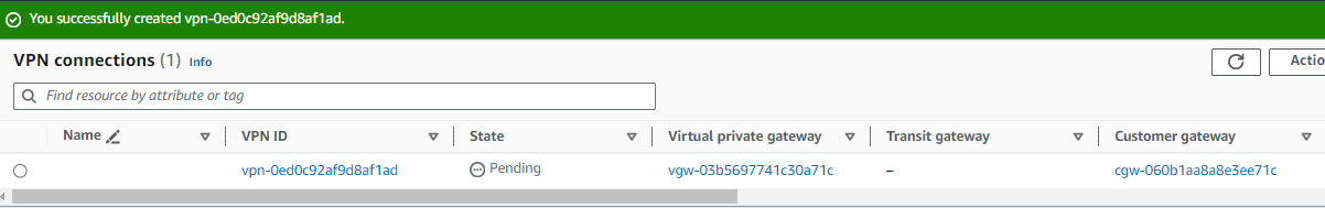
NOTE: Like in several AWS configuration, the Name of this VPN connection is a customer friendly tag which we ommited in this lab.
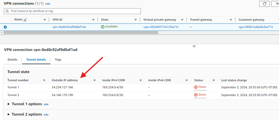
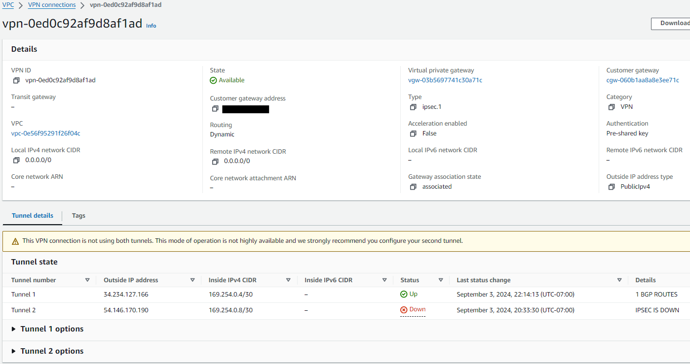
The VPN connection takes a few minutes to get created. Once we refresh the screen, we should see the State column showing **
Click on the newly created VPN. On the button section of the screen click-on Tunnel details. The IP addresses displayed in column Outside IP address are the AWS Public IP addresses to be used as the IPSec endpoints.
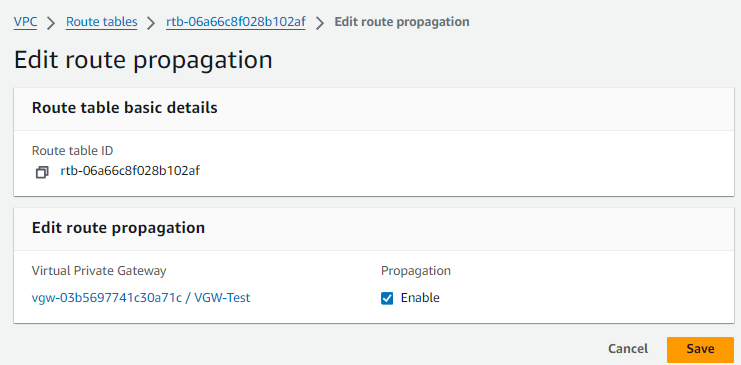
Step 5 - AWS : Propagate the Routes in the Route Table
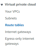
Finally, go to Virtual private cloud > Route tables
Select the Route Table and click on the Rotute propagation tab
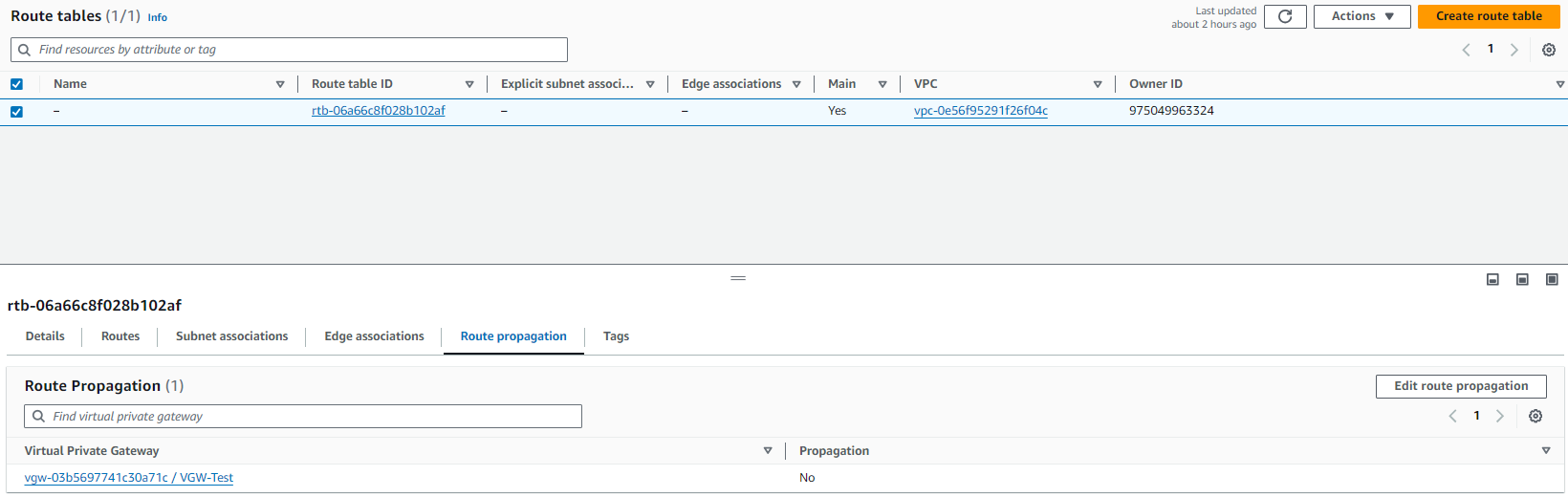
Enable the Route propagation checkbox and click Save
Step 6 - GNS3 : Conect Router to the Internet
I already have a GNS3 setup running with the the GNS3 VM (installation tutorial in the References section) and VMware® Workstation 17 Pro.
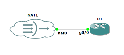
What I am using is a Cisco Router 7200 connected to a NAT Cloud
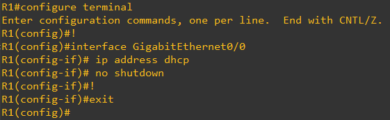
The first step is configure the Router to receive an IP Address via DHCP
1
2
3
4
5
6
7
configure terminal
!
interface GigabitEthernet0/0
 ip address dhcp
 no shutdown
!
exit
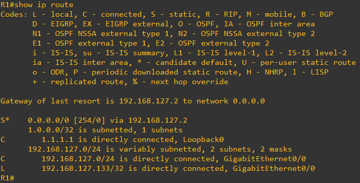
We must see the Routing table now having a Default Route installed installed in the Routing Table
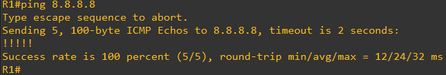
The Router must be able to ping a Host on the Internet, in this case we are pinging the well-known Google DNS server 8.8.8.8
Step 7 - GNS3 : Configure Router
1
2
3
4
5
6
7
8
9
10
11
12
13
14
15
16
17
18
19
20
21
22
23
24
25
26
27
28
29
30
31
32
33
34
35
36
37
38
39
40
41
42
43
44
45
46
47
48
49
50
51
52
53
54
55
56
57
58
59
!
! IKE Phase 1 Configs
!
crypto isakmp policy 200
  encryption aes 128
  authentication pre-share
  group 2
  lifetime 28800
  hash sha
exit
!
crypto keyring keyring-vpn-01
  local-address GigabitEthernet0/0
  pre-shared-key address 34.234.127.166 key cisco123
exit
!
crypto isakmp profile isakmp-vpn-01
  local-address GigabitEthernet0/0
  match identity address 34.234.127.166
  keyring keyring-vpn-01
exit
!
! IKE Phase 2 Configs
!
crypto ipsec transform-set ipsec-prop-vpn-01 esp-aes 128 esp-sha-hmac
  mode tunnel
exit
!
crypto ipsec profile ipsec-vpn-01
  set pfs group2
  set security-association lifetime seconds 3600
  set transform-set ipsec-prop-vpn-01
exit
!
crypto ipsec df-bit clear
crypto isakmp keepalive 10 10 on-demand
crypto ipsec security-association replay window-size 128
crypto ipsec fragmentation before-encryption
!
! Tunnel config
!
interface Tunnel1
  ip address 169.254.0.6 255.255.255.252
  tunnel source GigabitEthernet0/0
  tunnel destination 34.234.127.166
  tunnel mode ipsec ipv4
  tunnel protection ipsec profile ipsec-vpn-01
  ip tcp adjust-mss 1379
  no shutdown
exit
!
! BGP Configs
!
router bgp 65000
  neighbor 169.254.0.5 remote-as 64512
  neighbor 169.254.0.5 activate
  neighbor 169.254.0.5 timers 10 30 30
exit
!
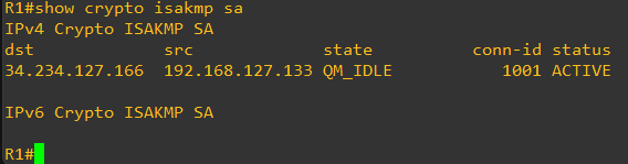
Once the configuration is applied, the status of the Crypto SA should be QM_IDLE in the output of show crypto isakmp sa
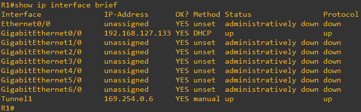
The status Tunnel interface should be up/up
We should also see a BGP peering established with the AWS VPN endpoint
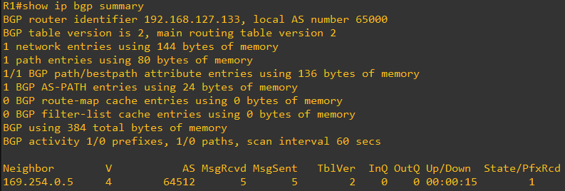
And thru this BGP peering, we should be receiving the AWS VPC CIDR
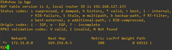
In this case, we have configured a loopback on the Router with IP address 1.1.1.1
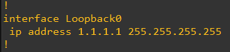
We will be advertising this loopback to AWS thru this same BGP session
1
2
3
4
5
configure terminal
!
router bgp 65000
  network 1.1.1.1 mask 255.255.255.255
!
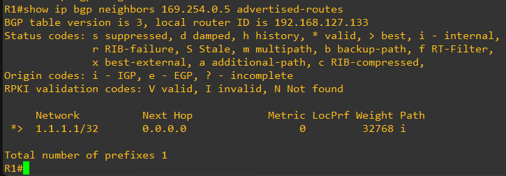
We confirm this IP address is advertised to the AWS VGW
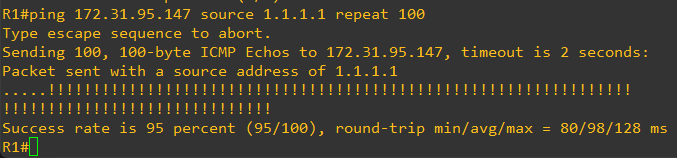
Step 8 - Validate connectivity using ICMP packets (ping test)
On the AWS Management Console go again to Virtual private network (VPN) > Site-to-Site VPN connections and observe the Status of Tunnel1 is Up
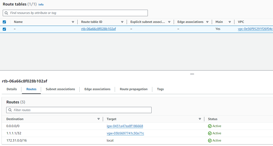
Go to Virtual private cloud > Route tables
Observe there is now an entry for 1.1.1.1 pointing to the VGW.
Finally, we will quickly spin up an EC2 instance in the VPC so we can ping to it from the Cisco Router in GNS3
Here how the EC2 instance looks like
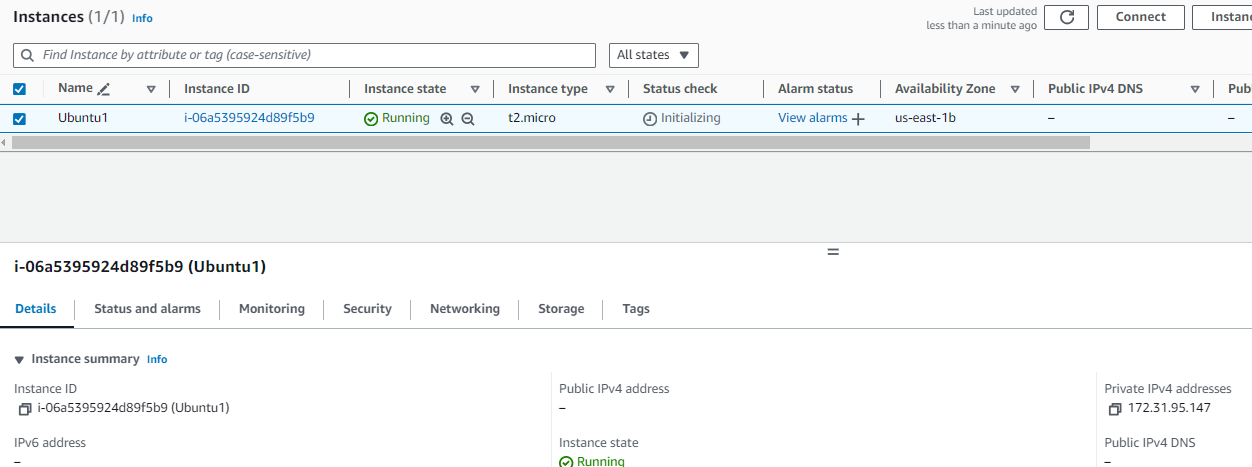
And finally, we have a successful ping test between the Cisco Router in GNS3 running in my personal laptop and an EC2 intance in a VPC in the AWS cloud